2 current sensor connection, Figure 4. current channel — low-voltage input, Cdb5490u – Cirrus Logic CDB5490U User Manual
Page 8
CDB5490U
8
DS923DB5
1.3.2
Current Sensor Connection
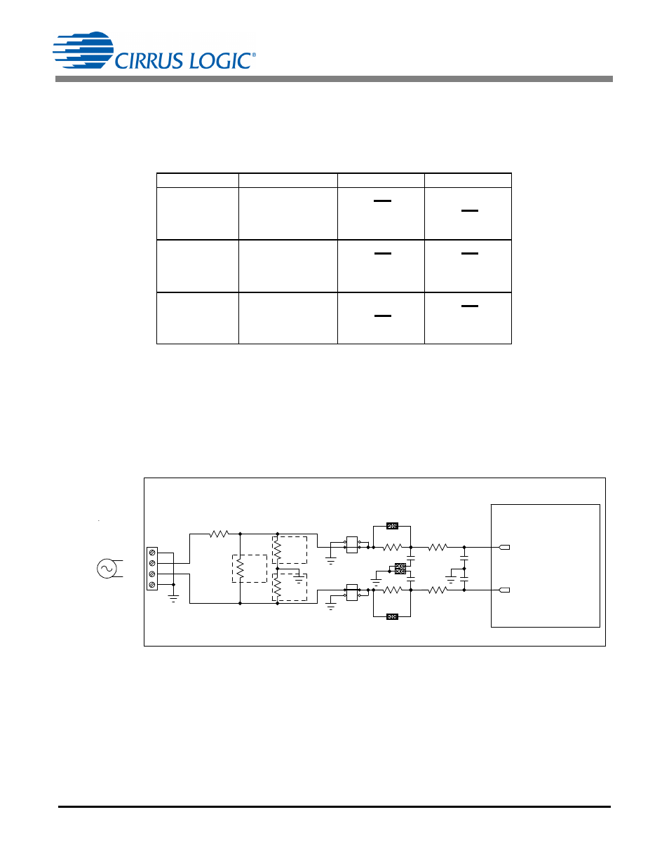
Current input options include an external signal (via screw terminals or XLR connectors) or GND. Table 2
illustrates the options available.
There are two input signal options for the current channel (IIN±). The CDB5490U evaluation board pro-
vides screw-type terminals (J1) or XLR connectors (J28) to connect an input signal to the current channel.
The screw terminals are labeled as IIN+ / IIN-. An R-C network at the channel input provides a simple,
configurable anti-alias filter (see Figure 4).
By installing jumpers on J8 to position IIN+, J7 to position IIN-, the input current signal is supplied from
the screw terminals or XLR connectors.
The CDB5490U evaluation board provides input shorting options for calibration and noise performance
measurements. With a jumper on J8 and J7 in the GND position, the inputs are connected to analog
ground (GND).
Table 2. Current Channel Input Signal Selection
INPUT
Description
J8
J7
IIN±
Selects External
Low-voltage,
Fully Differential
Signal
IIN±
Selects External
Low-voltage,
Single-ended
Signal
GND
Selects Grounding
the Input
O
IIN+
O O
IIN+
IIN+
GND
(Default)
O
IIN-
O O
IIN-
GND
IIN-
(Default)
O
IIN+
O O
IIN+
IIN+
GND
O
IIN-
O O
IIN-
GND
IIN-
O
IIN+
O O
IIN+
IIN+
GND
O
IIN-
O O
IIN-
GND
IIN-
IIN-
IIN+
GND
GND
CS5490
CDB5490U
250 mVp
J1
J7
J8
C5
0.033UF
C6
0.033UF
R11
NO POP
R1
100
R2
100
R9
NO POP
R13
NO POP
R49
1K
R50
1K
C34
0.033UF
C35
0.033UF
J44
J46
R51
0
J53/J56
J54
IIN+
IIN-
Figure 4. Current Channel — Low-voltage Input