Cirrus Logic CDB5490U User Manual
Features, General description
Copyright
Cirrus Logic, Inc. 2012
(All Rights Reserved)
Cirrus Logic, Inc.
CDB5490U
CDB5490U Engineering Board and GUI Software
Features
• Standalone Power Meter Application
• Voltage and Current Interfaces
• Low- and High-voltage Sensor Connections
• Adaptable Sensor Filters Onboard
• USB Communication with PC
• Isolated UART Communication
• Onboard C8051F342 Microcontroller
• Single Supply Operation from USB or an External +5V DC
Supply
• Onboard DC-DC Converter and Regulator
• LCD Power Monitor Display
• LabWindows
®
/ CVI
®
GUI Software
– Full Register Setup and Chip Control
– Simplified Register
– Quick Calibration Control
– FFT Analysis
– Time Domain Analysis
– Noise Histogram Analysis
• Voltage Reference Access
General Description
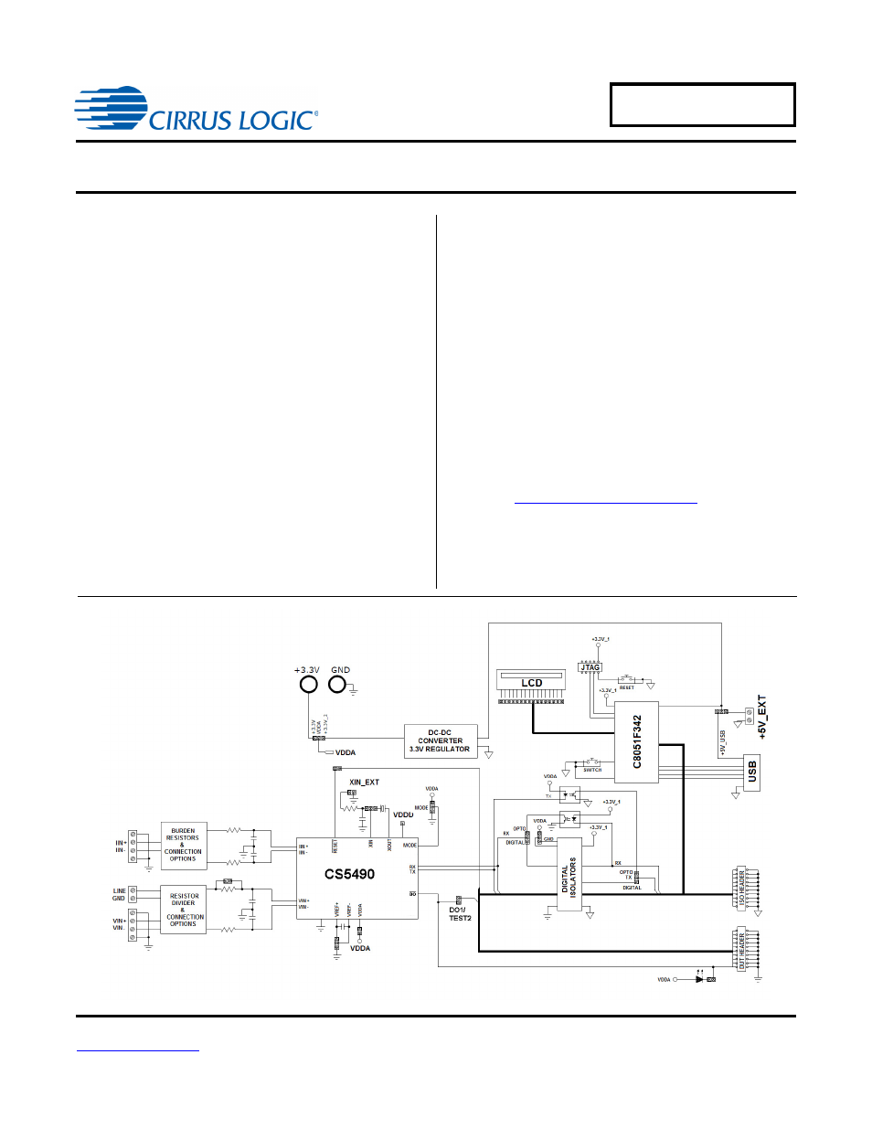
The CDB5490U is an extensive tool designed to evaluate the
functionality and performance of Cirrus Logic’s CS5490 power
measurement device.
Multiple analog input connection options, configuration input fil-
ters, direct and isolated digital interfaces, multiple power supply
options, an onboard programmable microcontroller, visual LEDs
with an LCD panel make the board a flexible and powerful cus-
tomer development tool for various power measurement
applications.
The GUI software provides easy and complete access and con-
trol to the onboard CS5490 device. In addition, it includes the
function of raw ADC data collection with time domain, frequency
domain, and histogram analysis.
Schematics in PADS™ PowerLogic™ format are available for
downloa
ORDERING INFORMATION
CDB5490U-Z
Evaluation Board
APR‘12
DS923DB5
Document Outline
- Features
- Table of Contents
- List of Figures
- 1. Hardware
- 2. Software
- 2.1 Installation Procedure
- 2.2 Using the Software
- 2.3 Start-up Window
- 2.4 Connect Menu
- 2.5 System Menu
- 2.5.1 Setup Window
- 2.5.1.1 Refresh Screen Button
- 2.5.1.2 Reset DUT Button
- 2.5.1.3 Save Config and Load Config Buttons
- 2.5.1.4 CS5490 MCLK Frequency
- 2.5.1.5 Configuration Registers
- 2.5.1.6 Pulse Control Register
- 2.5.1.7 Pulse Width and Pulse Rate Registers
- 2.5.1.8 Phase Compensation
- 2.5.1.9 Integrator Gain, System Gain
- 2.5.1.10 Sample Count, Cycle Count, Settle Time
- 2.5.1.11 ZXNUM
- 2.5.1.12 Epsilon
- 2.5.1.13 Mask Register
- 2.5.1.14 Temperature Registers
- 2.5.1.15 Zero-crossing Level and No Load Threshold
- 2.5.1.16 V Sag, V Swell, and I Overcurrent Registers
- 2.5.1.17 Register Checksum, SerialCtrl Registers
- 2.5.1 Setup Window
- 2.6 Calibration Window
- 2.7 Conversion Window
- 2.8 Cirrus Test Window
- 2.8.1 Data Collection Window
- 2.8.1.1 Time Domain / FFT/ Histogram Selector
- 2.8.1.2 Config Button
- 2.8.1.3 Collect Button
- 2.8.1.4 Output Button
- 2.8.1.5 Zoom Button
- 2.8.1.6 Channel Select Button
- 2.8.1.7 Output Button and Window
- 2.8.1.8 Configuration Window
- 2.8.1.9 Collecting Data Sets
- 2.8.1.10 Analyzing Data
- 2.8.1.11 Histogram Information
- 2.8.1.12 Frequency Domain Information
- 2.8.1.13 Time Domain Information
- 2.8.2 Data Collection to File Window
- 2.8.3 Setup and Test Window
- 2.8.1 Data Collection Window
- Appendix A. Bill Of Materials
- Appendix B. Schematics
- Appendix C. Layer Plots