2 current transformer power meter example, Figure 7. current transformer power meter, Cdb5490u – Cirrus Logic CDB5490U User Manual
Page 13
CDB5490U
DS923DB5
13
1.6.2
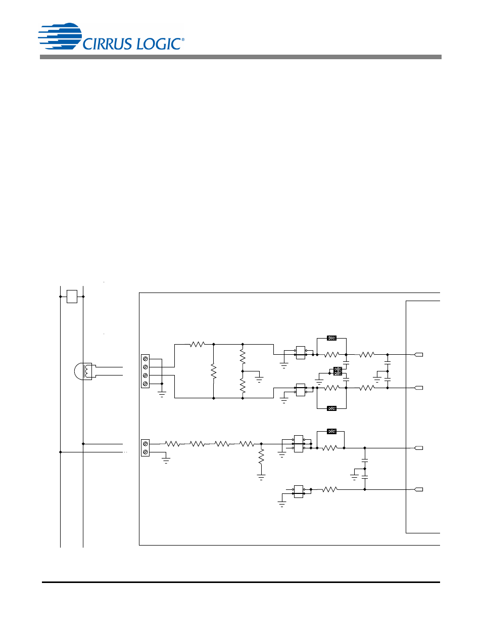
Current Transformer Power Meter Example
A slightly more expensive option is to use a current transformer (CT) to connect the AC current to the
CDB5490U evaluation board. Figure 7 depicts the voltage and current connections for a CT sensor and
its associated filter configurations.
NEVER “open circuit” a CT. Make sure that all signals are well connected before the power source is
turned on. Extreme care should be taken when connecting high-voltage signals to the CDB5490U evalu-
ation board.
The burden resistor (R11) is necessary in a CT application to convert the secondary current into voltage.
Knowledge of the current transformer turns ratio (N) is key to determining the proper CS5490 input voltage
(V
burden
) that the meter places on the system. The optimum secondary voltage (V
burden
) at the maximum
current input should be 10% less than the maximum channel voltage of 250mVp with I-channel
PGA = 10x. The secondary voltage (V
burden
) is determined by converting the primary current to the sec-
ondary current. Then the secondary current (I
burden
) can be converted into a voltage by Ohm's Law.
The secondary voltage (V
burden
) is sourced to the CS5490 through a simple low-pass, anti-alias filter, and
this voltage should not exceed the 250mVp.
Vburden Iburden Rburden
Iprimary
N
------------------------ Rburden
=
=
IIN-
IIN+
GND
GND
GND
LINE
CS
5490
CDB5490U
PH
AS
E
NEU
TRA
L
J1
J4
J7
J8
J11
J6
R5
1K
C5
0.033UF
C6
0.033UF
C9
0.027UF
C4
0.027UF
R11
2.2
R1
100
R2
100
R7 1K
R6 1K
R9
1K
R13
1K
R8 422K
R12 422K
R14 422K
R15 422K
R49
1K
R50
1K
C34
0.033UF
C35
0.033UF
J44
J46
R51
0
J45
J53
J54
IIN+
IIN-
VIN-
VIN+
Figure 7. Current Transformer Power Meter