Full-scale signal performance, Noise performance, Signal inputs – Cirrus Logic CS5372 User Manual
Page 9: Differential inputs - inr+/-, inf, Modulator performance
CS5371 CS5372
DS255F3
9
3. MODULATOR PERFORMANCE
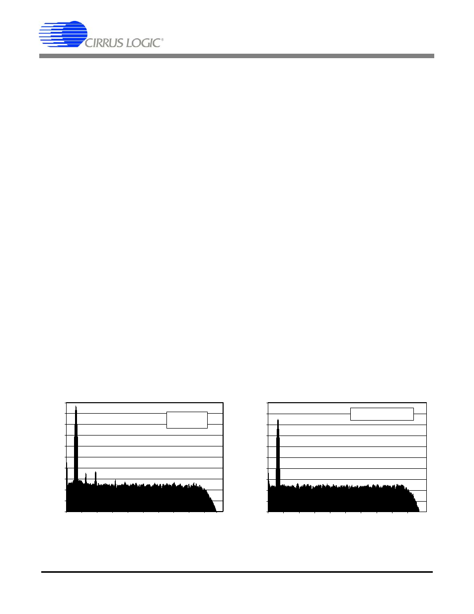
Figures 4 and 5 illustrate the spectral performance
of the CS5371/72 modulators when combined with
the CS5376A or CS5378 digital filter. The plots
were created from ten averaged 1024 point FFTs.
3.1.
Full-scale Signal Performance
Figure 4 illustrates the full-scale signal perfor-
mance of the CS5371/72 modulators and digital fil-
ter using a 31.25 Hz input signal and a 1000 SPS
output word rate. The outstanding full-scale signal
characteristics of the CS5371/72 modulators are
shown, with no harmonic components exceeding -
120 dB. Analysis of this data set yields a signal-to-
noise ratio (SNR) of 124.0 dB and a signal-to-dis-
tortion ratio (SDR) of 119.0 dB. Note that the full-
scale signal peak in Figure 4 shows a slightly re-
duced amplitude due to spectral smearing associ-
ated with the FFT windowing function, and is a
purely digital phenomenon.
3.2.
Noise Performance
Figure 5 illustrates the noise performance of the
CS5371/72 modulators and digital filter using a
31.25 Hz -24 dB input signal at a 1000 SPS output
word rate. The outstanding noise characteristics of
the CS5371/72 modulators are shown, with the av-
eraged noise components consistently below the
-150 dB level. Analysis of this data set yields a dy-
namic range of 124.7 dB. Note that the 0.7 dB
variation between the signal-to-noise calculation in
Figure 4 and the dynamic range calculation in Fig-
ure 5 is not modulator dependent and results from
jitter in the test signal generator when producing a
full-scale output, as evidenced by the skirt sur-
rounding the signal peak below the -140 dB level in
Figure 4.
4. SIGNAL INPUTS
The CS5371/72 modulators use a switched capac-
itor architecture for the analog signal inputs, which
has increased jitter tolerance compared with con-
tinuous time signal input stages.
4.1.
Differential Inputs - INR+/-, INF+/-
The analog signal inputs are differential and use
four pins: INR+, INR-, INF+, and INF-. Two inputs,
INR+ and INF+, are connected to the positive half
of the differential signal, while two inputs, INR- and
INF-, are connected to the negative half. The INR+
and INR- pins are switched capacitor ‘rough
charge’ inputs that pre-charge the internal sam-
pling capacitor before it is connected to the INF+
and INF- fine input pins.
The full-scale analog signal span is defined by the
voltage applied across the VREF+ and VREF-
pins. A 2.5 volt reference input sets full-scale sig-
nals as 5 volts peak-to-peak, fully differential. Dif-
ferential inputs increase the dynamic range of
Figure 4. 1024 Point FFT plot with a 31.25 Hz
input at Full-scale, ten averages
-200
-180
-160
-140
-120
-100
-80
-60
-40
-20
0
0
50
100
150
200
250
300
350
400
450
500
dB
Hz
S/N = 124.0 dB
S/D = 119.0 dB
-200
-180
-160
-140
-120
-100
-80
-60
-40
-20
0
0
50
100
150
200
250
300
350
400
450
500
dB
Hz
Dynamic Range = 124.7 dB
Figure 5. 1024 Point FFT plot with a 31.25 Hz
input at -24 dB, ten averages