Dc electrical characteristics, Digital interface characteristics – Cirrus Logic CS44800 User Manual
Page 9
DS632F1
9
CS44800
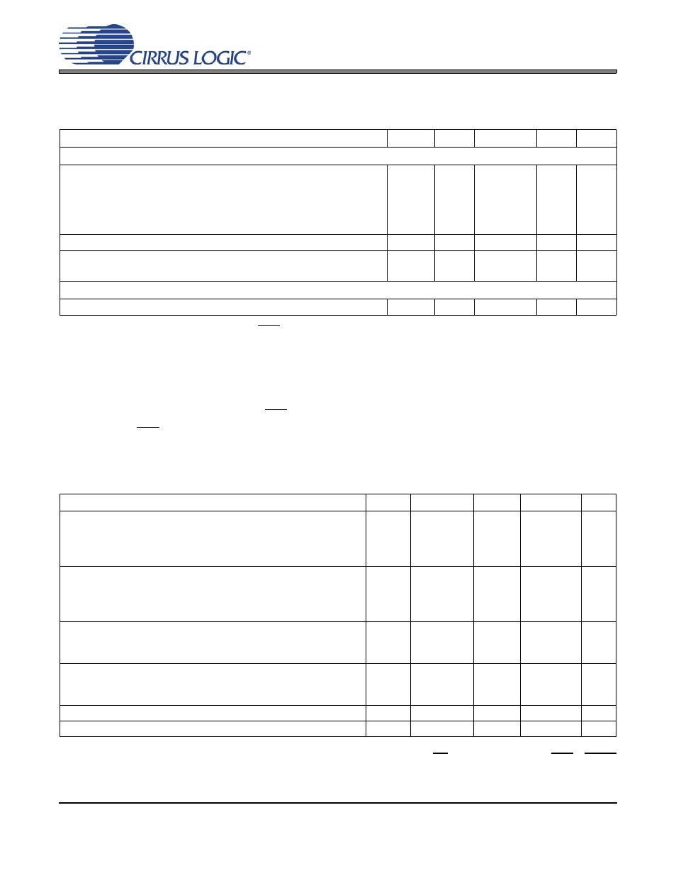
DC ELECTRICAL CHARACTERISTICS
(GND = 0 V, all voltages with respect to ground; DAI_MCLK = 12.288 MHz, XTAL = 24.576 MHz, PWM Switch
Rate = 384 kHz unless otherwise specified.)
4.
Normal operation is defined as RST = HI with a 997 Hz, 0 dBFS input.
5.
Current consumption increases with increasing XTAL clock rates and PWM switch rates. Variance be-
tween DAI clock rates is negligible.
6.
I
LC
measured with no external loading on the SDA pin.
7.
Valid with PSRR function enabled and the recommended external ADC (CS4461) and filtering.
8.
Power down mode is defined as RST pin = LOW with all clock and data lines held static.
9.
When RST pin = LOW, the internal oscillator is active to provide a valid clock for the SYS_CLK output.
DIGITAL INTERFACE CHARACTERISTICS
(GND = 0 V, all voltages with respect to ground)
10. Serial Port signals include: SYS_CLK, DAI_MCLK, DAI_SCLK, DAI_LRCK, DAI_SDIN1-4
Control Port signals include: SCL/CCLK, SDA/CDOUT, AD0/CS, AD1/CDIN, INT, RST, MUTE
PWM signals include: PWMOUTA1-B4, PSR_MCLK, PSR_SYNC, PSR_DATA, PS_SYNC, GPIO[6:0]
Parameter
Symbol
Min
Typ
Max
Units
Normal Operation
Power Supply Current
VD = 2.5 V
VDX = 3.3 V
VDP = 3.3 V
VLS = 3.3 V
VLC = 3.3 V
I
D
I
DX
I
DP
I
LS
I
LC
-
-
-
-
-
150
2
1.2
150
250
-
-
-
-
-
mA
mA
mA
µA
µA
Power Dissipation
VD=2.5 V, VDX = VDP = VLS = VLC = 3.3 V
-
387
500
mW
Power Supply Rejection Ratio
(1 kHz)
(60 Hz)
PSRR
-
-
15
40
-
-
dB
dB
Power-Down Mode
Power Supply Current
All Supplies except VDX
I
pd
-
80
-
µA
Parameters
Symbol Min
Typ
Max
Units
High-Level Input Voltage
XTAL
PWM Interface
Serial Audio Interface
Control Interface
V
IH
0.7xVDX
0.7xVDP
0.7xVLS
0.7xVLC
-
-
-
-
-
-
-
-
V
V
V
V
Low-Level Input Voltage
XTAL
PWM Interface
Serial Audio Interface
Control Interface
V
IL
-
-
-
-
-
-
-
-
0.2xVDX
0.2xVDP
0.2xVLS
0.2xVLC
V
V
V
V
High-Level Output Voltage at I
o
= -2 mA
PWM Interface
Serial Audio Interface
Control Interface
V
OH
VDP-1.0
VLS-1.0
VLC-1.0
-
-
-
-
-
-
V
V
V
Low-Level Output Voltage at I
o
= 2 mA
PWM Interface
Serial Audio Interface
Control Interface
V
OL
-
-
-
-
-
-
0.45
0.45
0.45
V
V
V
Input Leakage Current
I
in
-
-
±10
µA
Input Capacitance
-
-
8
pF