Typical connection diagram, Figure 1. typical connection diagram, Cs43l22 – Cirrus Logic CS43L22 User Manual
Page 9
DS792F2
9
CS43L22
Confidential Draft
3/4/10
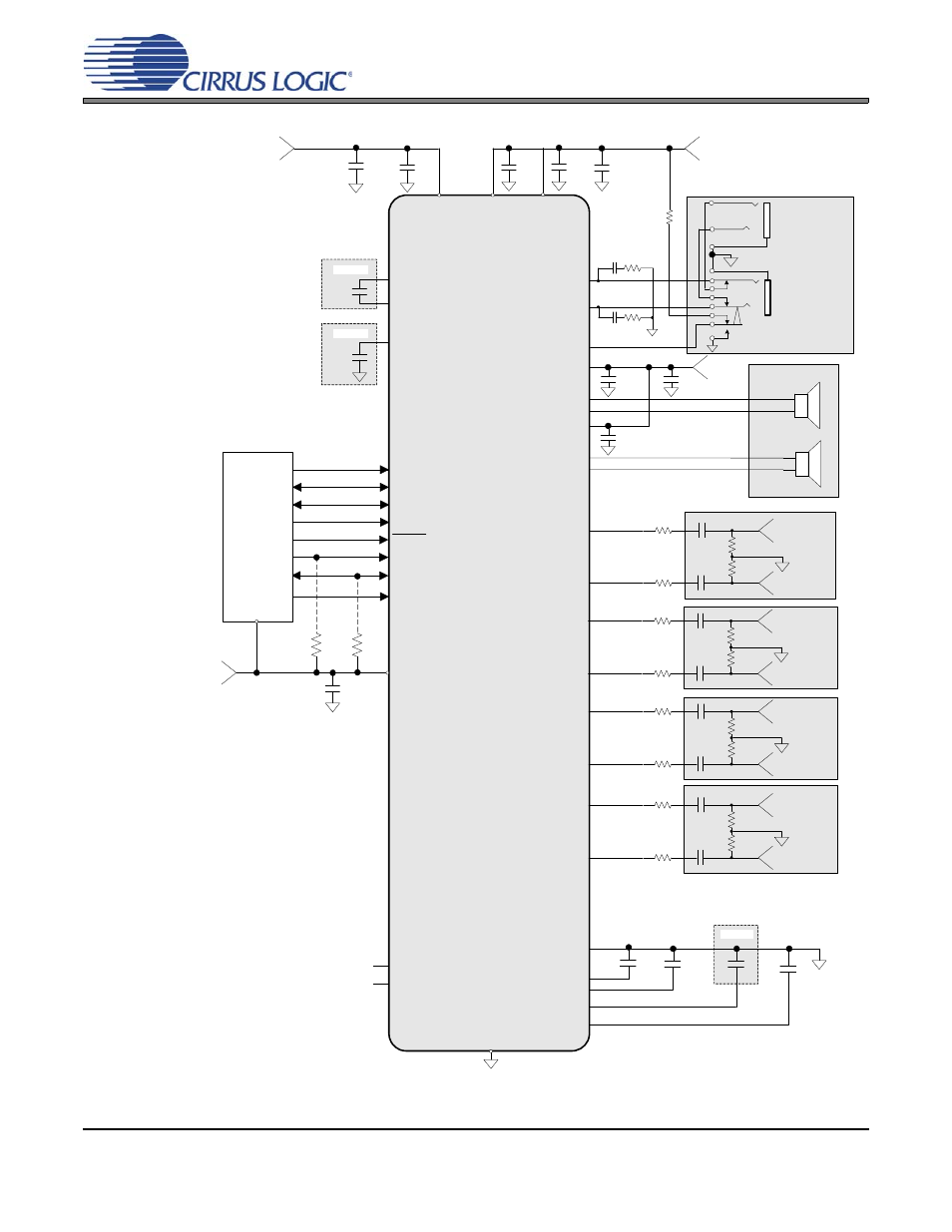
2. TYPICAL CONNECTION DIAGRAM
Note 3
Note 2
Note 1
1 µF
+1.8 V to +2.5 V
0.1 µF
1 µF
DGND
VL
0.1 µF
+1.8 V to +3.3 V
SCL
SDA
RESET
2 k
Ω
LRCK
Digital Audio
Processor
MCLK
SCLK
VD
SDIN
CS43L22
2 k
Ω
+1.8 V to +2.5 V
HP/LINE_OUTB
HP/LINE_OUTA
AIN1A
Left 1
100 k
Ω
100
Ω
AIN1B
Right 1
0.1 µF
VA
Headphone Out
Left & Right
Line Level Out
Left & Right
FLYP
FLYN
-VHPFILT
51.1
Ω
0.022 µF
100 k
Ω
100
Ω
SPKR_OUTA+
SPKR_OUTA-
SPKR/HP
51.1
Ω
0.022 µF
1 µF
1 µF
0.1 µF
+VHP
1 µF
VQ
AGND
* Capacitors must be C0G or equivalent
1 µF
**
**
See Note 4
SPKR_OUTB+
SPKR_OUTB-
1 µF
VP
VP
+1.6 V to
+5 V
Stereo Speakers
AIN2A
Left 2
100 k
Ω
100
Ω
AIN2B
Right 2
100 k
Ω
100
Ω
1 µF
1 µF
0.1 µF
0.1 µF
Analog
Input 1
Analog
Input 2
10 µF
47 k
Ω
Notes:
1. Recommended values for the default charge pump switching
frequency. The required capacitance follows an inverse
relationship with the charge pump’s switching frequency. When
increasing the switching frequency, the capacitance may
decrease; when lowering the switching frequency, the
capacitance must increase.
2. Larger capacitance reduces the ripple on the internal
amplifier’s supply. This may reduce the distortion at higher
output power levels.
3. Additional bulk capacitance may be added to improve PSRR
at low frequencies.
4. Series resistance in the path of the power supplies must be
avoided. Any voltage drop on VHP will directly impact the
negative charge pump supply (-VHPFILT) and clip the audio
output.
AIN3A
Left 3
100 k
Ω
100
Ω
AIN3B
Right 3
100 k
Ω
100
Ω
1 µF
1 µF
Analog
Input 3
AIN4A
Left 4
100 k
Ω
100
Ω
AIN4B
Right 4
100 k
Ω
100
Ω
1 µF
1 µF
Analog
Input 4
FILT+
10 µF
150 pF
150 pF
AFILTA
AFILTB
**
Low ESR, X7R/X5R dielectric capacitors.
**
**
**
**
**
**
**
**
*
*
TSTO
TSTO
AD0
Figure 1. Typical Connection Diagram