2 invert signal polarity (invert_a) bit 6, 3 invert signal polarity (invert_b) bit 5, Figure 18. atapi block diagram – Cirrus Logic CS4398 User Manual
Page 31: Cs4398
DS568F1
31
CS4398
7.3.1
Channel B Volume = Channel A Volume (VOLB=A) Bit 7
Function:
When set to 0 (default), the AOUTA and AOUTB volume levels are independently controlled by the A and
the B Channel Volume Control Bytes.
When set to 1, the volume on both AOUTA and AOUTB are determined by the A Channel Attenuation and
Volume Control Bytes, and the B Channel Bytes are ignored.
7.3.2
Invert Signal Polarity (Invert_A) Bit 6
Function:
When set to 1, this bit inverts the signal polarity of channel A.
When set to 0 (default), this function is disabled.
7.3.3
Invert Signal Polarity (Invert_B) Bit 5
Function:
When set to 1, this bit inverts the signal polarity of channel B.
When set to 0 (default), this function is disabled.
7.3.4
ATAPI Channel Mixing and Muting (ATAPI4:0) Bits 4-0
Default = 01001 - AOUTA=aL, AOUTB=bR (Stereo)
Function:
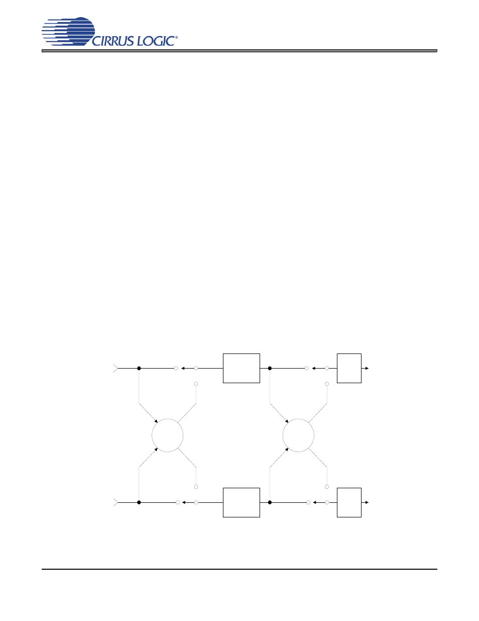
The CS4398 implements the channel-mixing functions of the ATAPI CD-ROM specification. Refer to Ta-
ble and Figure 18 for additional information.
Figure 18. ATAPI Block Diagram
Σ
Σ
A Channel
Volume
Control
AoutA
AoutB
Left Channel
Audio Data
Right Channel
Audio Data
B Channel
Volume
Control
MUTE
MUTE