Dc electrical characteristics, Cs4398 dc electrical characteristics – Cirrus Logic CS4398 User Manual
Page 17
DS568F1
17
CS4398
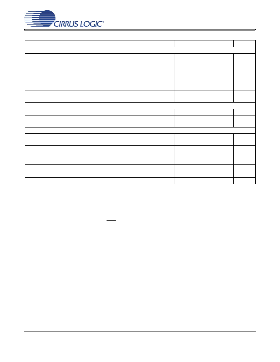
DC ELECTRICAL CHARACTERISTICS
16. Normal operation is defined as RST pin = High with a 997 Hz, 0 dBFS input sampled at the highest Fs for
each speed mode, and open outputs, unless otherwise specified.
17. I
A
measured with no loading on the AMUTEC and BMUTEC pins.
18. I
LC
measured with no external loading on pin 11 (SDA).
19. Power-Down mode is defined as RST pin = Low with all clock and data lines held static.
20. Valid with the recommended capacitor values on FILT+ and V
Q
as shown in the “Typical Connection Dia-
21. This current is sourced/sinked directly from the VA supply.
Parameters
Symbol
Min
Typ
Max
Units
Normal Operation
(Note 16)
Power Supply Current
V
A
= 5 V (Note 17)
V
ref
= 5 V
V
D
= 5 V
V
D
= 3.3 V
Interface current (Note 18)
I
A
I
ref
I
D
I
D
I
LC
I
LS
-
-
-
-
-
-
25
1.5
25
18
2
80
28
2
38
27
-
-
mA
mA
mA
mA
µA
µA
Power Dissipation
VA = 5 V, VD = 5 V
VA = 5 V, VD = 3.3 V
-
-
258
192
340
240
mW
mW
Power-Down Mode
(Note 19)
Power Supply Current
I
pd
-
200
-
µA
Power Dissipation
VA = 5 V, VD = 5 V
VA = 5 V, VD = 3.3 V
-
-
1
1
-
-
mW
mW
All Modes of Operation
Power Supply Rejection Ratio (Note 20)
(1 kHz)
(60 Hz)
PSRR
-
-
60
40
-
-
dB
dB
Common Mode Voltage
V
Q
-
0.5•V
A
-
V
Max Current draw from VQ
I
Qmax
-
1
-
µA
FILT+ Nominal Voltage
-
0.93•V
A
-
V
Maximum MUTEC Drive Current
(Note 21)
-
3
-
mA
MUTEC High-Level Output Voltage
V
OH
VA
V
MUTEC Low-Level Output Voltage
V
OL
0
V