Figure 7. de-emphasis curve, fs = 44.1 khz, 5 internal high-pass filter, 6 digital interface format – Cirrus Logic CS4354 User Manual
Page 15: 7 internal power-on reset, Figure 8. internal power-on reset circuit, Section 4.6, Figure 7, Cs4354
DS895F2
15
CS4354
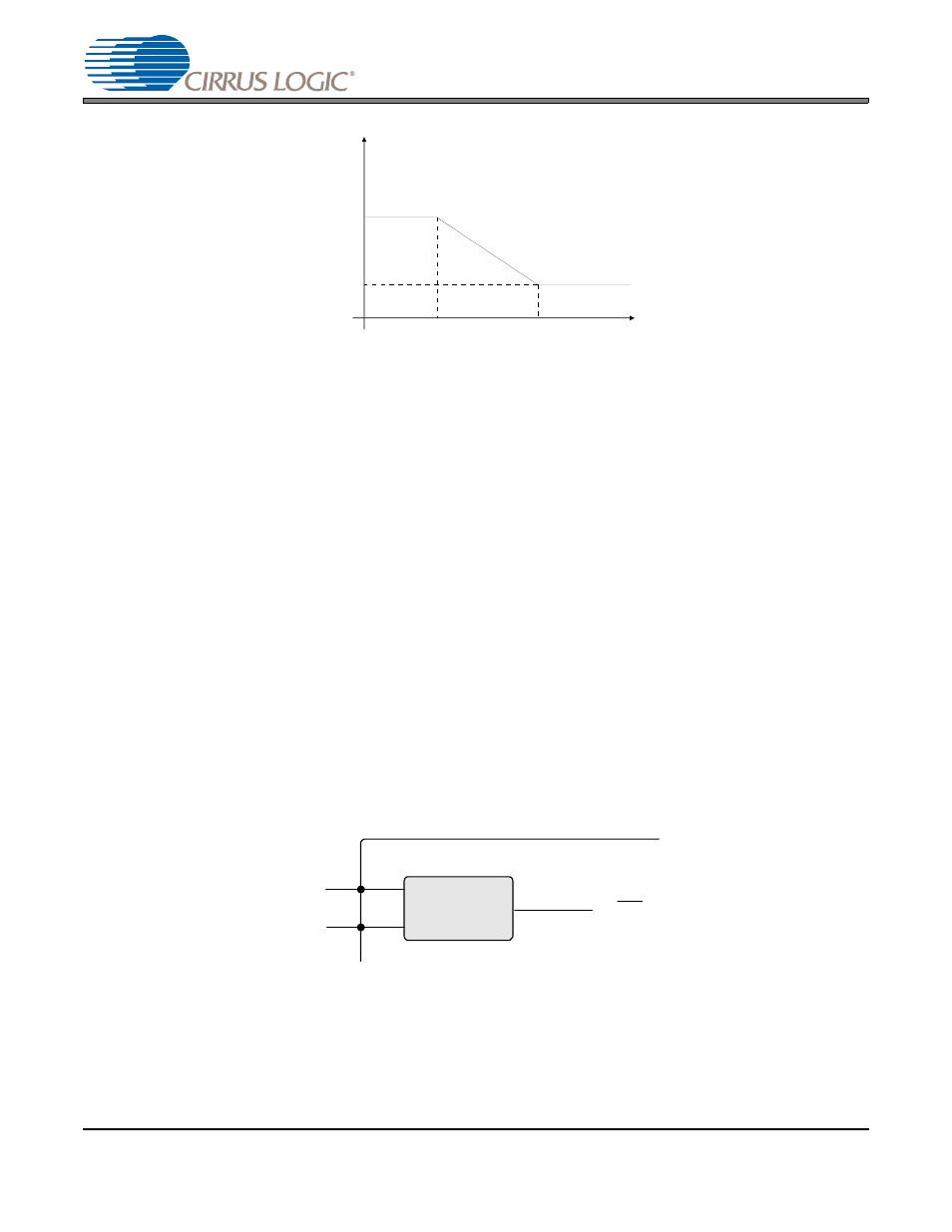
Figure 7. De-Emphasis Curve, Fs = 44.1 kHz
Note:
De-emphasis is only available in Single-Speed Mode.
4.5
Internal High-Pass Filter
The CS4354 includes an internal digital high-pass filter. This filter prevents a constant digital offset from cre-
ating a DC voltage on the analog output pins. The filter’s corner frequency is well below the audio band; see
“Combined Digital and On-Chip Analog Filter Characteristics” on page 7
for filter specifications.
4.6
Digital Interface Format
The device accepts audio samples in the industry standard I²S format only.
For an illustration of the required relationship between the LRCK, SCLK and SDIN, see
. SDIN is valid on the rising edge of SCLK. For more information about serial audio formats, refer to Cirrus
Logic Application Note AN282: The 2-Channel Serial Audio Interface: A Tutorial, available at
4.7
Internal Power-On Reset
The CS4354 features an internal power-on reset (POR) circuit. This circuit monitors the VA supply and au-
tomatically asserts or releases an internal reset of the DAC’s digital circuitry when the supply reaches de-
fined thresholds (see
“Internal Power-On Reset Threshold Voltages” on page 10
). No external clocks are
required for the POR circuit to function.
Figure 8. Internal Power-On Reset Circuit
Gain
dB
-10dB
0dB
Frequency
T2 = 15 µs
T1=50 µs
F1
F2
3.183 kHz
10.61 kHz
Power-On Reset
Circuit
VA
GND
reset
(internal)