4 serial clock, Figure 6. cs4354 data format (i·s), 1 external serial clock mode – Cirrus Logic CS4354 User Manual
Page 14: 2 internal serial clock mode, 1 de-emphasis control, Figure 6. cs4354 data format (i²s), Table 5. internal sclk frequencies, Cs4354
14
DS895F2
CS4354
4.4
Serial Clock
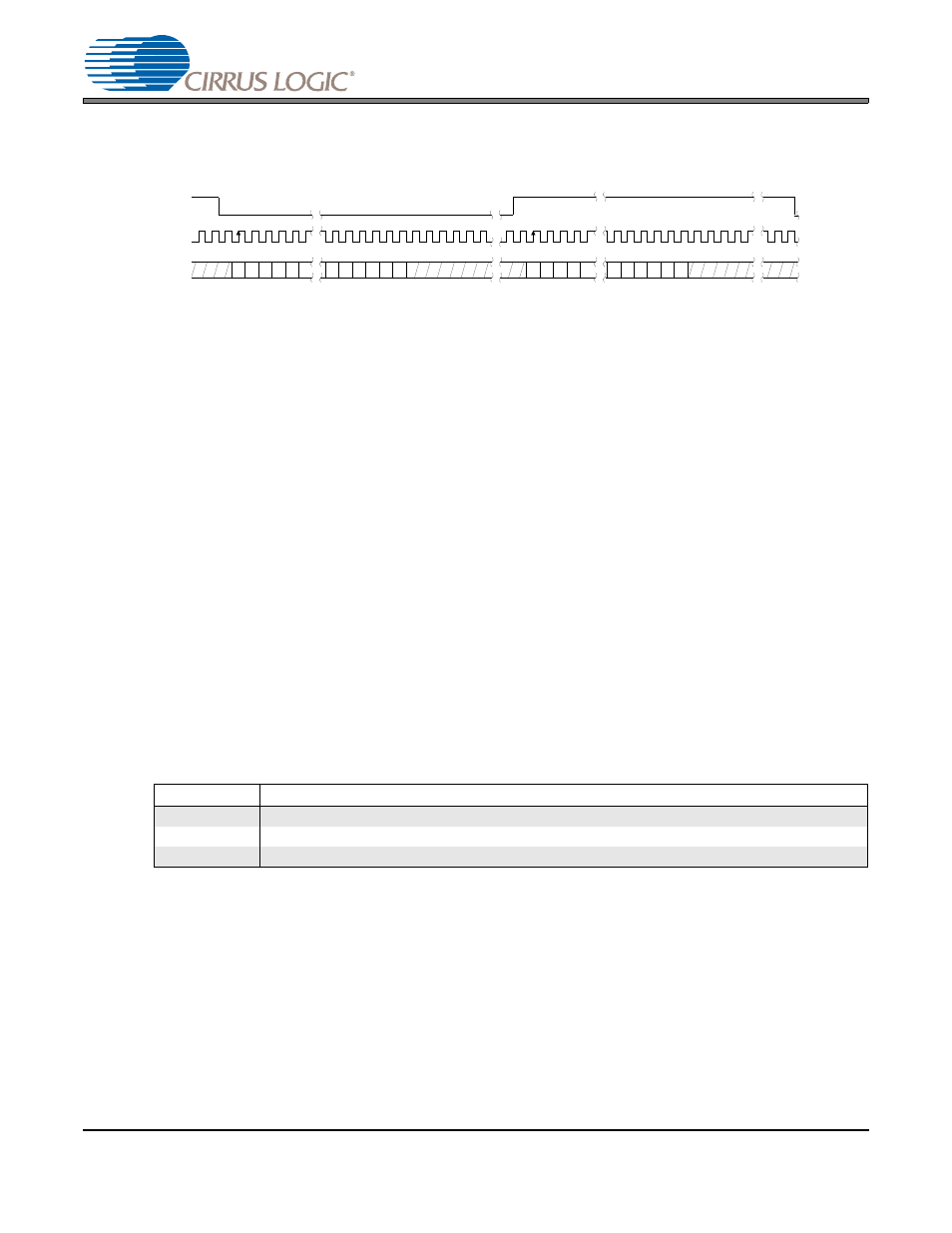
The serial clock controls the shifting of data into the input data buffers. The CS4354 supports both external
and internal serial clock generation modes. Refer to
for a diagram of the I²S data format.
In order to support selectable de-emphasis without a dedicated pin, pin 5 (SCLK/DEM) functions both as
a serial clock input and a de-emphasis select. In typical applications where de-emphasis is not required,
the SCLK/DEM pin is the input for an external serial clock - this is known as the External Serial Clock
Mode. To enable de-emphasis selection, the Internal Serial Clock Mode has to be used. Sections
and
describe this feature in detail.
4.4.1
External Serial Clock Mode
The CS4354 will enter the External Serial Clock Mode when 16 low to high transitions are detected on the
SCLK/DEM pin during any phase of the LRCK period. When this mode is enabled, the Internal Serial
Clock Mode and de-emphasis filter are disabled (see
for flow diagram).
In the External Serial Clock Mode, the CS4354 will support up to 24-bit I²S data, with data valid on the
rising edge of SCLK.
4.4.2
Internal Serial Clock Mode
The CS4354 will switch to Internal Serial Clock Mode if no low to high transitions are detected on the
SCLK/DEM pin for 2 consecutive frames of LRCK (see
for flow diagram). In the Internal Serial
Clock Mode, the serial clock is internally derived and synchronous with MCLK and LRCK. The
SCLK/LRCK frequency ratio is either 32, 48, or 64 depending on the speed mode and MCLK frequency.
Operation in this mode is identical to operation with an external serial clock synchronized with LRCK. This
mode allows access to the digital de-emphasis function. Refer to
for details (all frequencies listed
as multiples of LRCK frequency).
Table 5. Internal SCLK Frequencies
4.4.2.1
De-Emphasis Control
The device includes on-chip digital de-emphasis.
shows the de-emphasis curve for Fs equal to
44.1 kHz. The frequency response of the de-emphasis curve scales with changes in the sample rate, Fs.
The de-emphasis error will increase for sample rates other than 44.1 kHz.
When the SCLK/DEM pin is connected to VL (internal SCLK mode), the 44.1 kHz de-emphasis filter is
activated. When the SCLK/DEM pin is connected to GND, the de-emphasis filter is disabled. For more
information see
“Internal Serial Clock Mode” on page 14
De-emphasis selection is disabled in the external SCLK mode.
Speed Mode
MCLK =
128x
192x
256x
384x
512x
768x
1024x
SSM
-
-
64x
48x
64x
64x
64x
DSM
-
48x
-
-
-
-
-
QSM
-
32x
32x
-
-
-
-
LR C K
S C L K
Left C ha nnel
R ig ht C ha n nel
SDIN
+3 +2 +1
+5 +4
MSB
-1 -2 -3 -4 -5
+3 +2 +1
+5 +4
-1 -2 -3 -4
MSB
LSB
LSB
Figure 6. CS4354 Data Format (I²S)