Cirrus Logic CS4354 User Manual
V stereo dac with 2-v, Ground-centered output, Cs4354
Copyright
Cirrus Logic, Inc. 2011
(All Rights Reserved)
5-V Stereo DAC with 2-V
RMS
Ground-Centered Output
Features
Advanced multibit delta–sigma modulator
101 dB A-weighted dynamic range
–86 dB THD+N
Single-ended ground-centered analog
architecture
–
No DC-blocking capacitors required
–
Integrated inverting charge pump
–
Filtered line-level outputs
–
2 V
RMS
full-scale output
Low-latency digital filtering
Supports sample rates up to 192 kHz
24-bit I²S input
+5-V analog supply with integrated inverting
charge pump and regulator for core logic, and
+1.8-V to +5-V interface power supplies
50-mW power consumption
14-pin SOIC, lead-free assembly
Description
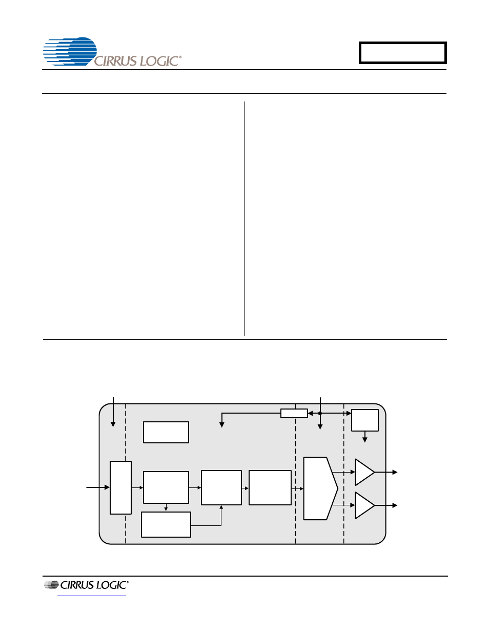
The CS4354 is a complete stereo digital-to-analog sys-
tem including digital interpolation, third-order multi-bit
delta–sigma digital-to-analog conversion, digital de-em-
phasis, analog filtering, and on-chip 2 V
RMS
line-level
driver from a 5 V supply.
The advantages of this architecture include ideal differ-
ential linearity, no distortion mechanisms due to resistor
matching errors, no linearity drift over time and temper-
ature, high tolerance to clock jitter, and a minimal set of
external components.
These features are ideal for cost-sensitive, two-channel
audio systems including video game consoles, Blu-Ray
Disc
®
and DVD players, set-top boxes, digital TVs, and
DAB/DMB devices.
The CS4354 is available in a 14-pin SOIC package in
Commercial (–40°C to +85°C) grade. The CDB4354
Customer Demonstration Board is also available for de-
vice evaluation and implementation suggestions.
Please see
“Ordering Information” on page 23
for com-
plete details.
PCM Serial
Audio Port
Lev
el
Sh
ift
e
r
I²S Serial
Audio Input
Multibit
Modulator
Interpolation
Filters + HPF
Left Channel
Right Channel
Power-On
Reset
Auto Speed
Mode Detect
Analog Supply (VA)
+5 V
Inverting
Charge
Pump
1.8V reg
-VA
Interface Supply (VL)
+1.8V to +5V
Ground-Centered,
2 Vrms Line Level
Outputs
DAC
Sept '11
DS895F2
CS4354
Document Outline
- 1. Pin Descriptions
- 2. Characteristics and Specifications
- Recommended Operating Conditions
- Absolute Maximum Ratings
- DAC Analog Characteristics
- Combined Digital and On-Chip Analog Filter Characteristics
- Switching Specifications - Serial Audio Interface
- Digital Interface Characteristics
- Internal Power-On Reset Threshold Voltages
- DC Electrical Characteristics
- 2.1 Digital I/O Pin Characteristics
- 3. Typical Connection Diagram
- 4. Applications
- 5. Combined Digital and On-chip Analog Filter Response Plots
- Figure 10. Single-Speed Stopband Rejection
- Figure 11. Single-Speed Transition Band
- Figure 12. Single-Speed Transition Band (detail)
- Figure 13. Single-Speed Passband Ripple
- Figure 14. Double-Speed Stopband Rejection
- Figure 15. Double-Speed Transition Band
- Figure 16. Double-Speed Transition Band (detail)
- Figure 17. Double-Speed Passband Ripple
- Figure 18. Quad-Speed Stopband Rejection
- Figure 19. Quad-Speed Transition Band
- Figure 20. Quad-Speed Transition Band (detail)
- Figure 21. Quad-Speed Passband Ripple
- 6. Parameter Definitions
- 7. Package Information
- 8. Ordering Information
- 9. Revision History