Cirrus Logic CS4348 User Manual
Page 7
7
CS4344/5/8
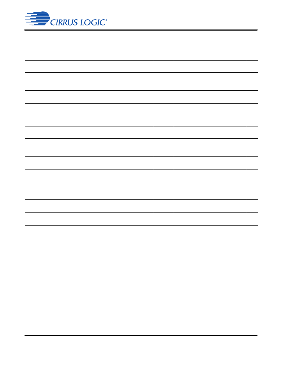
COMBINED INTERPOLATION & ON-CHIP ANALOG FILTER RESPONSE
(The filter characteristics have been normalized to the sample rate (Fs) and can be referenced to the desired sam-
ple rate by multiplying the given characteristic by Fs.) See
Notes:
2. Response is clock dependent and will scale with Fs.
3. For Single-Speed Mode, the Measurement Bandwidth is 0.5465 Fs to 3 Fs.
For Double-Speed Mode, the Measurement Bandwidth is 0.577 Fs to 1.4 Fs.
For Quad-Speed Mode, the Measurement Bandwidth is 0.7 Fs to 1 Fs.
4. Refer to
.
5. De-emphasis is available only in Single-Speed Mode.
6. Amplitude vs. Frequency plots of this data are available in
.
Parameter
Symbol
Min
Typ
Max
Unit
Combined Digital and On-chip Analog Filter Response—Single-Speed Mode
to -0.1 dB corner
to -3 dB corner
0
0
-
-
.35
.4992
Fs
Fs
Frequency Response 10 Hz to 20 kHz
-.175
-
+.01
dB
StopBand
.5465
-
-
Fs
StopBand Attenuation
50
-
-
dB
Group Delay
tgd
-
10/Fs
-
s
De-emphasis Error
Fs = 32 kHz
Fs = 44.1 kHz
Fs = 48 kHz
-
-
-
-
-
-
+1.5/+0
+.05/-.25
-.2/-.4
dB
dB
dB
Combined Digital and On-chip Analog Filter Response—Double-Speed Mode
to +0.1 dB corner
to -3 dB corner
0
0
-
-
.22
.501
Fs
Fs
Frequency Response 10 Hz to 20 kHz
-.15
-
+.15
dB
StopBand
.5770
-
-
Fs
StopBand Attenuation
55
-
-
dB
Group Delay
tgd
-
5/Fs
-
s
Combined Digital and On-chip Analog Filter Response—Quad-Speed Mode
to -0.1 dB corner
to -3 dB corner
0
0
-
-
0.110
0.469
Fs
Fs
Frequency Response 10 Hz to 20 kHz
-.12
-
+0
dB
StopBand
0.7
-
-
Fs
StopBand Attenuation
51
-
-
dB
Group Delay
tgd
-
2.5/Fs
-
s