Pin descriptions – Cirrus Logic CS4348 User Manual
Page 4
4
CS4344/5/8
1. PIN DESCRIPTIONS
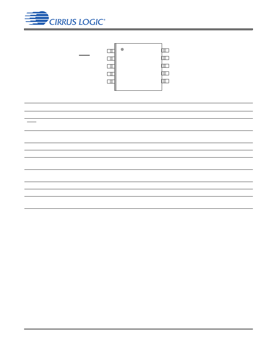
Pin Name
#
Pin Description
SDIN
1
Serial Audio Data Input (Input) - Input for two’s complement serial audio data.
DEM/SCLK
2
De-Emphasis/External Serial Clock Input (Input) - used for deemphasis filter control or external serial
clock input.
LRCK
3
Left Right Clock (Input) - Determines which channel, Left or Right, is currently active on the serial audio
data line.
MCLK
4
Master Clock (Input) - Clock source for the delta-sigma modulator and digital filters.
VQ
5
Quiescent Voltage (Output) - Filter connection for internal quiescent voltage.
FILT+
6
Positive Voltage Reference (Output) - Positive reference voltage for the internal sampling
circuits.
AOUTL
7
Left Channel Analog Output (Output) - The full scale analog output level is specified in the Analog Char-
acteristics specification table.
GND
8
Ground (Input) - ground reference.
VA
9
Analog Power (Input) - Positive power for the analog and digital sections.
AOUTR
10 Right Channel Analog Output (Output) - The full scale analog output level is specified in the Analog
Characteristics specification table.
SDIN
AOUTR
DEM/SCLK
VA
LRCK
GND
MCLK
AOUTL
VQ
FILT+
1
2
3
4
5
6
7
8
9
10