List of tables, 1 quick start guide, Quick start guide – Cirrus Logic CDB42L55 User Manual
Page 4: Figure 1.quick start board layout
4
DS773DB1
CDB42L55
1 QUICK START GUIDE
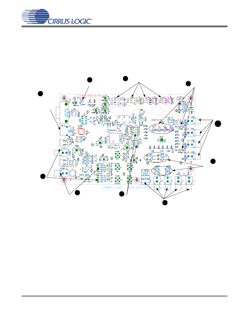
The following figure is a simplified quick-start guide made for user convenience. The guide configures the board with
a 1.8 V power supply to VLDO, VA and VCP and a 3.3 V power supply to VL. The user may choose from steps 7
through 10 depending on the desired measurement. Refer to
for details on how the various
components on the board interface with each other in different board configuration modes. Refer to
for descriptions on control settings in the Cirrus FlexGUI software.
.
Figure 1. Quick Start Board Layout
Set desired jumper
settings for
J12,J4,J2 and J3.
1
2
3
4
5
6
7
Set jumper settings for VL to 3.3V
and VCP,VLDO and VA to 1.8V
J48,J53,J52, J74, J7 and
J11 should be shunted
Set Board Power setting to USB
Left pins on J109 and
J104 should be
shunted
Provide digital inputs to
the board either through
the S/PDIF optical or
RCA connectors or
through the PSIA I/O
header J78.
Receive digital outputs from the board
either through the S/PDIF optical or
RCA phono connectors or through the
PSIA I/O header J40.
Monitor analog outputs via HP or Line Channel RCA
connectors or HP stereo jack
Apply analog inputs
9
10
Connect USB to board. Open Flex
GUI software on PC and load
quick setup script.
8