4 analog input filters, 1 active single-ended-to-differential input filter, 2 passive differential input filter – Cirrus Logic CDB4244 User Manual
Page 15: Section 4, Star
DS900DB2
15
CDB4244
4 ANALOG INPUT FILTERS
The CDB4244 makes it possible to realize two different analog input filter options for interfacing with the CS4244: a
convenient active single-ended-to-differential filter to showcase maximum analog input performance, and an option-
al passive differential filter to minimize component count. Refer to AN340: CS4234/4244 Filter Considerations for a
detailed discussion of the theory and design decisions behind each filter. The following sections highlight the use
cases of each filter.
4.1
Active Single-Ended-to-Differential Input Filter
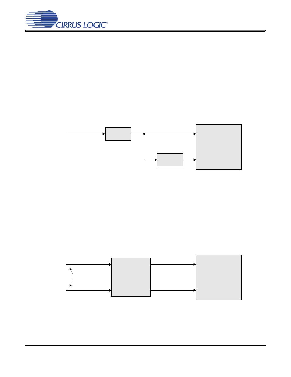
By default, the CDB4244 is configured with an active single-ended-to-differential input filter network on each
input channel to allow a simple single-ended signal to be connected to each of the board’s analog inputs.
The filter network converts the single-ended signal into a differential signal to interface with the differential
analog inputs of the CS4244, while minimizing source impedance in order to achieve maximum analog input
performance.
highlights the signal flow of this filter.
Figure 6. Active Single-Ended-to-Differential Input Filter Block Diagram
Use of this filter network requires a dual-rail ±12-V power supply to power the operational amplifiers em-
ployed in the design. Note that the amplitude of the single-ended input signal is doubled by the differential
conversion. As such, the full-scale input voltage that can actually be applied at the input of the filter is 6 dB
below the full-scale input voltage specified in the CS4244 data sheet.
4.2
Passive Differential Input Filter
Alternatively, each input channel of the CDB4244 can be configured with a passive differential input filter
network to reduce component count at the cost of performance. In this configuration, a differential input sig-
nal is connected to each analog input of the CDB4244, filtered through a passive network, and presented
directly to the CS4244 analog inputs.
highlights the signal flow of this filter.
Figure 7. Passive Differential Input Filter Block Diagram
Because no active circuit elements are used in this design, the dual-rail ±12-V power supply can be removed
completely if no active output filters are in use (refer to
). If only the +5-V power sup-
ply remains in use, the CDB4244 can be powered solely from the PC USB port when the board power is
configured as specified in
.
Single-Ended Input
AIN+
AIN-
Non-Inverting
Buffer
Inverting
Buffer
CS4244
Differential Input
AIN+
AIN-
Passive Filter
Network
CS4244