1 terminal configuration – WIKA DI35 User Manual
Page 16
6 Commissoning, operation
16
WIKA operating instructions digital indicator DI35-M
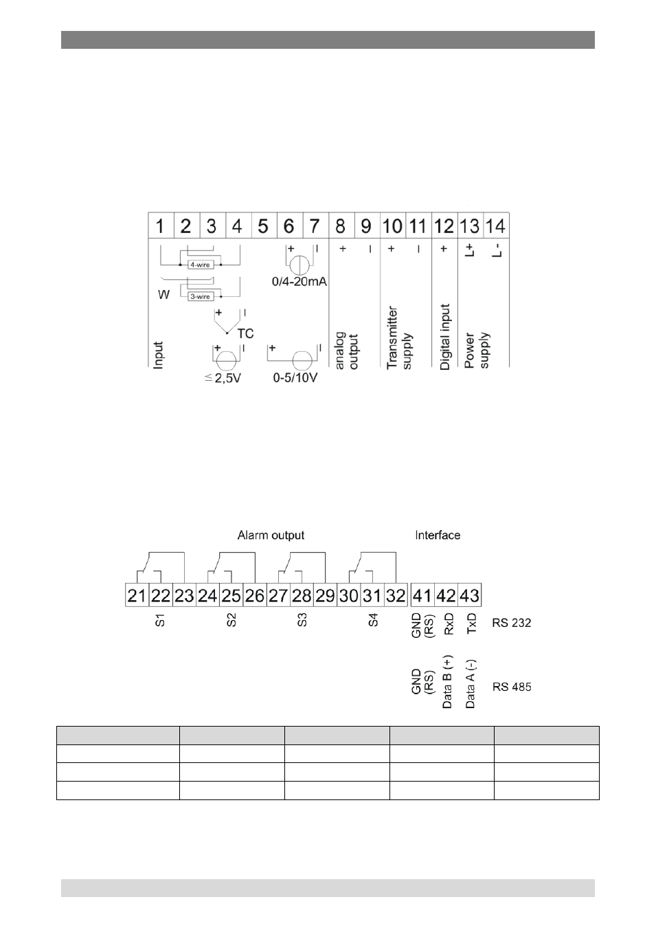
6.2.1 Terminal configuration
Lower terminal connector
The power supply, the input signal, the transmitter supply and the analogue
output signal have to be connected to the lower terminal connector.
The mounting screws for the transmitter supply and the analogue output
signal are only available if these options have been chosen.
Upper terminal connector
The switching contacts (relays) and the serial interface have to be connected
to the upper terminal connector.
The mounting screws for the switching contacts and the interface are only
available if these options have been choosen.
Relay 1 (S1) Relay 2 (S2) Relay 3 (S3) Relay 4 (S4)
Normally closed 21
24
27
30
Normally open
22
25
28
31
Com
23
26
29
32