Appendix 1: fm-csa installation drawing – WIKA T53 User Manual
Page 27
GB
11178648.04 03/2010 GB/D/F/E
WIKA Operating Instructions Temperature Transmitter T53
27
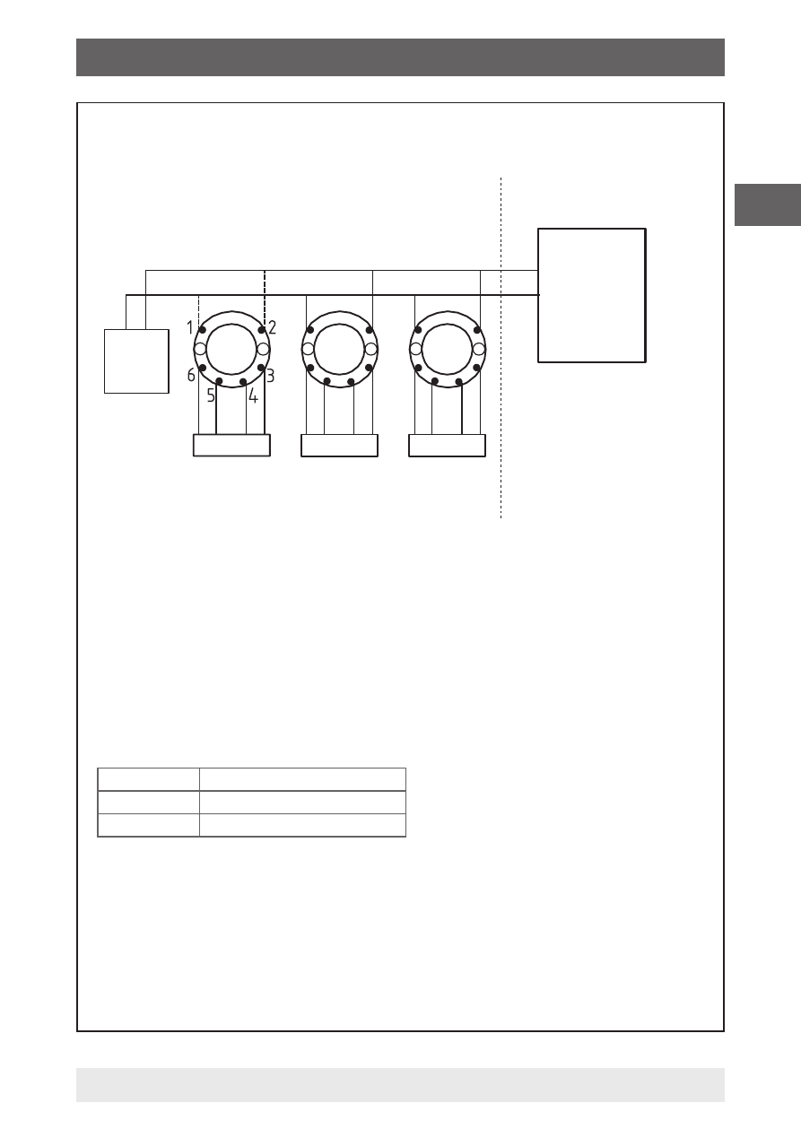
Sensor
Sensor
Sensor
Installation of Model T53.10.0NI
Approved
Termina-
tion
Terminal 3, 4, 5, 6
V
t
or U
o
: 5.71 V
l
t
or l
o
:
8.4 mA
P
t
or P
o
: 12 mW
C
a
or C
o
: 40 µF
L
a
or L
o
: 200 mH
Terminal 1, 2
C
i
: 2.0 nF
L
i
: 1µH
The device must not be
connected to any
associated apparatus
which uses or generates
more than 250 VRMS
32 V
Class 2
Power Supply
Unclassified Location
Class I, Division 2, Groups A, B, C, D
or
Class I, Zone 2, IIC
Hazardous (classified) Location
T1 ... T4
-40 °C ≤ Ta ≤ +85 °C
T5
-40 °C ≤ Ta ≤ +75 °C
T6
-40 °C ≤ Ta ≤ +60 °C
See Installation notes.
Installation Drawing 11175631.01
3/6
Appendix 1: FM-CSA Installation Drawing
See also other documents in the category WIKA Measuring instruments:
- 890.09.2190 (44 pages)
- A-10 (96 pages)
- A2G-50 (52 pages)
- A2G-55 (36 pages)
- AC-1 (88 pages)
- C-2 (24 pages)
- D-10-7 (112 pages)
- D-20-9 (51 pages)
- D-20-9 (35 pages)
- DG-10 (112 pages)
- DP-10 (44 pages)
- DPT-10 (96 pages)
- DPT-10 (92 pages)
- GCS-1 (76 pages)
- HP-2 (84 pages)
- IL-10 (31 pages)
- IPT-10 (56 pages)
- IPT-10 (48 pages)
- IPT-10 (28 pages)
- IPT-10 (36 pages)
- IS-20-F (7 pages)
- IS-20-F (43 pages)
- IS-20-H (7 pages)
- UT-10 (42 pages)
- UT-10 (52 pages)
- IUT-10 (78 pages)
- LH-10 (60 pages)
- LH-20 (60 pages)
- LS-10 (60 pages)
- MG-1 (92 pages)
- MH-1 (11 pages)
- MH-2 (9 pages)
- MHC-1 (84 pages)
- N-10 (35 pages)
- O-10 (108 pages)
- OT-1 (60 pages)
- P-30 (92 pages)
- PSA-31 (124 pages)
- PSD-30 (128 pages)
- R-1 (92 pages)
- S-10 (35 pages)
- S-11 (102 pages)
- S-20 (52 pages)
- S-20 (96 pages)
- SL-1 (21 pages)