Commissioning, operation, 3 block diagram, T53.10 – WIKA T53 User Manual
Page 21
GB
11178648.04 03/2010 GB/D/F/E
WIKA Operating Instructions Temperature Transmitter T53
21
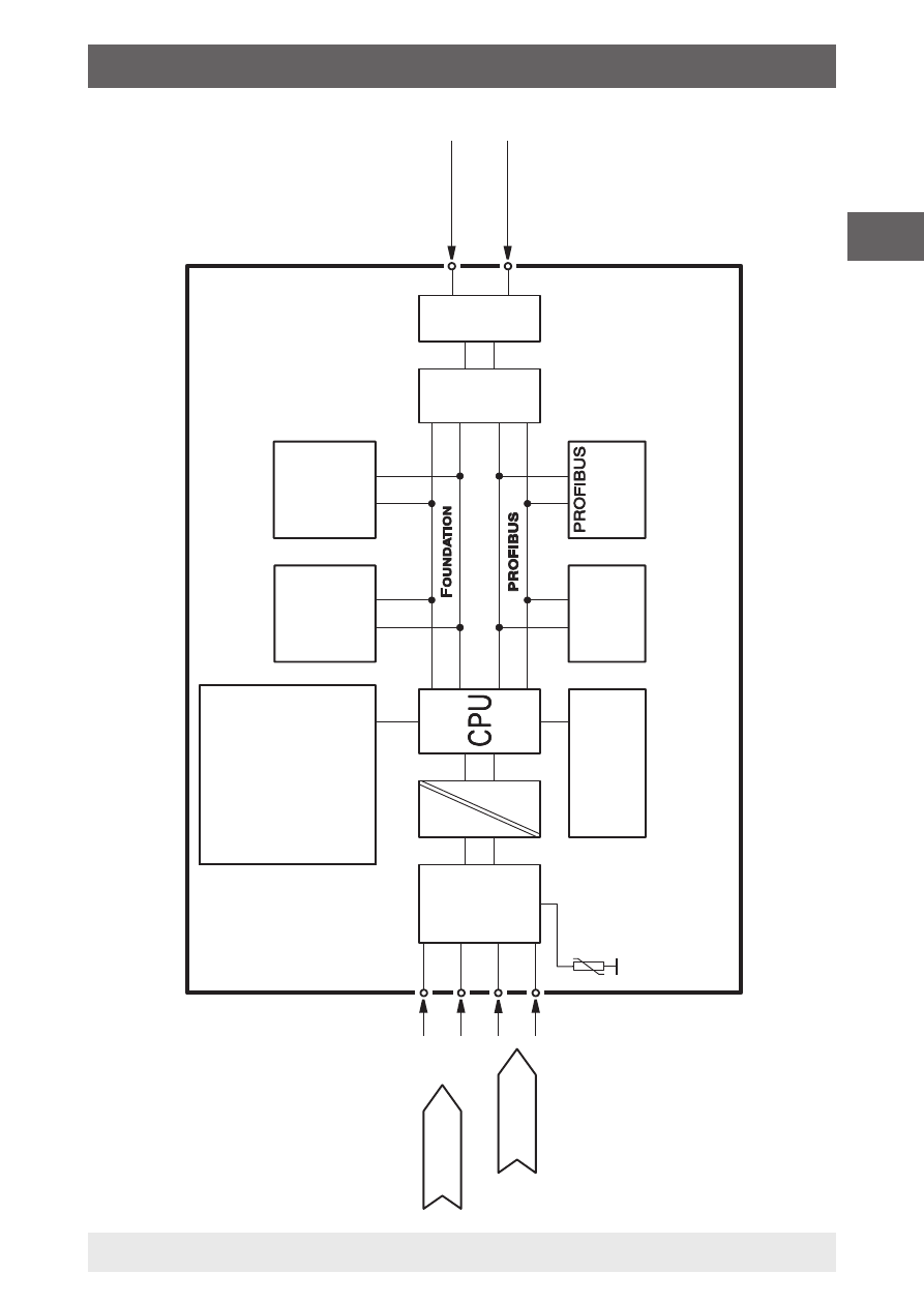
6.3 Block diagram
Galv
anic
isolation
Bus connection
1
2
Input 1
Selectable Inputs:
■
Resistance thermometer
■
Thermocouple
■
Bipolar mV
■
Ohm
■
Potentiometer
Input 2
Internal
CJC
Analogue
to
Digital con
ver
ter
Tr
ans
ducer block
Input 1
Input 2
Differ
ence
Av
er
age
Redundancy
Terminal temper
atur
e
Engineering units
Diagnostics
Table linearisation
Polynominal linearisation
Pr
ocess calibr
ation
EEPR
OM
Complete configur
ation
Corr
ektion coefficients
Factor
y settings
Automatic
communication
switch
Function block
s
AI1, AI2 PID
LA
S
Foundation fieldbus Pr
otocol
Ex circuit
3
4
5
6
Function block
s AI1,
AI2
Pr
otocol
T53.10
6. Commissioning, operation
See also other documents in the category WIKA Measuring instruments:
- 890.09.2190 (44 pages)
- A-10 (96 pages)
- A2G-50 (52 pages)
- A2G-55 (36 pages)
- AC-1 (88 pages)
- C-2 (24 pages)
- D-10-7 (112 pages)
- D-20-9 (51 pages)
- D-20-9 (35 pages)
- DG-10 (112 pages)
- DP-10 (44 pages)
- DPT-10 (96 pages)
- DPT-10 (92 pages)
- GCS-1 (76 pages)
- HP-2 (84 pages)
- IL-10 (31 pages)
- IPT-10 (56 pages)
- IPT-10 (48 pages)
- IPT-10 (28 pages)
- IPT-10 (36 pages)
- IS-20-F (7 pages)
- IS-20-F (43 pages)
- IS-20-H (7 pages)
- UT-10 (42 pages)
- UT-10 (52 pages)
- IUT-10 (78 pages)
- LH-10 (60 pages)
- LH-20 (60 pages)
- LS-10 (60 pages)
- MG-1 (92 pages)
- MH-1 (11 pages)
- MH-2 (9 pages)
- MHC-1 (84 pages)
- N-10 (35 pages)
- O-10 (108 pages)
- OT-1 (60 pages)
- P-30 (92 pages)
- PSA-31 (124 pages)
- PSD-30 (128 pages)
- R-1 (92 pages)
- S-10 (35 pages)
- S-11 (102 pages)
- S-20 (52 pages)
- S-20 (96 pages)
- SL-1 (21 pages)