Appendix 1: fm-csa installation drawing – WIKA T53 User Manual
Page 25
GB
11178648.04 03/2010 GB/D/F/E
WIKA Operating Instructions Temperature Transmitter T53
25
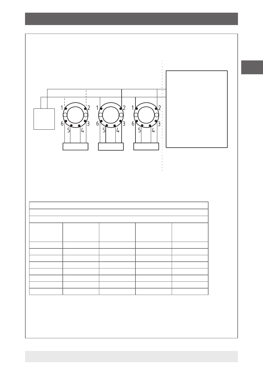
Appendix 1: FM-CSA Installation Drawing
Sensor
Sensor
Sensor
Model T53.10.0IS
Approved
Termina-
tion
Terminal 3, 4, 5, 6
V
t
or U
o
: 5.71 V
l
t
or l
o
:
8.4 mA
P
t
or P
o
: 12 mW
C
a
or C
o
: 40 µF
L
a
or L
o
: 200 mH
The device must not be
connected to any
associated apparatus
which uses or generates
more than 250 VRMS
Associated Apparatus
Barrier or
FISCO Supply
with
entity Parameters:
Unclassified Location
UM ≤ 250 V
V
oc
or U
o
≤ V
max
or U
i
l
sc
or l
o
≤ l
max
or l
i
P
o
≤ P
i
C
a
or C
o
≥ C
i
+ C
cable
L
a
or L
o
≥ L
i
or L
cable
Class I, Division 1, Groups A, B, C, D
or
Class I, Zone 0, IIC
Hazardous (classified) Location
Terminal 1, 2
Class I, Zone 0, Ex ia IIC, Entity / FISCO
IS, Class I, Division 1, Group A, B, C, D Entity / FISCO
Barrier type Linear barrier Trapezoid
barrier
Suitable
for FISCO
systems
Suitable
for FISCO
systems
T1 ... T4
Ta ≤ +85 °C Ta ≤ +75 °C Ta ≤ +85 °C Ta ≤ +85 °C
T5
Ta ≤ +70 °C Ta ≤ +65 °C Ta ≤ +60 °C Ta ≤ +60 °C
T6
Ta ≤ +60 °C Ta ≤ +45 °C Ta ≤ +45 °C Ta ≤ +45 °C
V
max
or Ui 30 V
30 V
17.5 V
15 V
l
max
or li
120 mA
300 mA
250 mA
900 mA
Pi
0.84 W
1.3 W
2.0 W
5.32 W
Ci
2.0 nF
2.0 nF
2.0 nF
2.0 nF
Li
1 µH
1 µH
1 µH
1 µH
See Installation notes.
Installation Drawing 11175631.01
1/6