Options and accessories – WIKA DPGT40 User Manual
Page 17
GB
WIKA operating instructions differential pressure transmitter, model DPGT40
17
14093267.01 03/2014 GB/D/F/E
6. Commissioning, operation / 7. Options and accessories
6.3 Setting up a voltage supply
The voltage supply is made via a power supply unit or a control unit which
provides the energy limitation.
The power supply for the pressure transmitter must be made via an energy-
limited electrical circuit in accordance with section 9.3 of UL/EN/IEC 61010-1, or
an LPS to UL/EN/IEC 60950-1, or class 2 in accordance with UL1310/UL1585
(NEC or CEC). The power supply must be suitable for operation above 2,000 m
should the pressure transmitter be used at this altitude.
7. Options and accessories
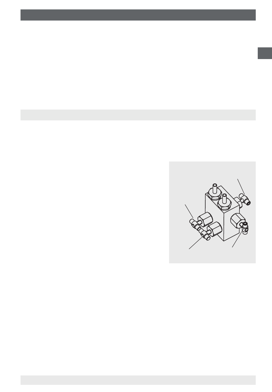
7.1 4-way valve manifold
■
Isolation of the ⊕ and ⊖ process lines for removing or testing the measuring
instrument without interrupting the running process operation.
Protection of the instrument against
excessive overpressure loading, such as
in pressure tests and undefined operating
conditions (including intermittent shutdown).
■
Pressure compensation for zero point
checking with running processes, and
avoiding one-sided overpressure loading
during start-up and operation phases (with
opened pressure compensating valve).
■
Venting the measuring lines with liquid
media and flushing of the measuring lines,
in order to remove contamination.
Vent valve
Shut-off valve
⊖ side
Shut-off valve
⊕ side
Pressure
compensating valve
Specifications for handling
■
Sequence of operations to start measurement
1. Open the pressure compensating valve (middle valve spindle)
2. Open the shut-off valve for the negative media chamber (⊖, right-hand valve)
and the positive media chamber (⊕, left-hand valve)
3. Close the pressure compensating valve
■
Sequence of operations to flush/vent the measuring lines
1. Start: Open the shut-off valve for the ⊕ and ⊖ media chamber, open the
pressure compensating valve and vent valve
2. Finish: Close the pressure compensating valve and vent valve