Specifications – WIKA DPGT40 User Manual
Page 10
GB
WIKA operating instructions differential pressure transmitter, model DPGT40
10
14093267.01 03/2014 GB/D/F/E
3. Specifications
For further specifications see the corresponding product label, WIKA data sheet
and the order documentation.
Designation of terminal connectors
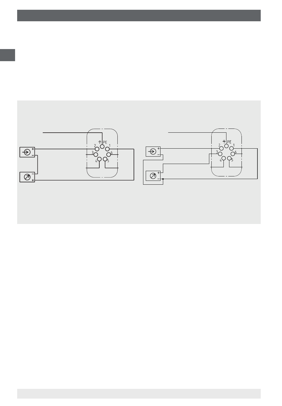
The exact pin assignments can be found in the following drawings. In addition, the
pin assignment, output signal and the required power supply are stated on the
product label.
The following diagram shows the standard terminal assignment. For customer-
specific designs, the terminal assignment on the product label must be followed.
2-wire system
4 … 20 mA
3-wire system
0 … 20 mA, 4 … 20 mA and 0 ... 10 V
Earth, connected to
case 1)
U
B
+/I+
0 V/GND
Evaluation
(display)
1) This connection must not be used
for equipotential bonding. The
instrument must be incorporated in the
equipotential bonding via the process
connection.
Terminals 3 and 4: for internal use only
Terminals 5 and 6: reset zero point
Evaluation
(display)
Power supply
Power supply
Explanation of the terminal assignments used:
U
B
+
Positive terminal of power supply
0 V/Sig-/GND Negative terminal of power supply and output signal
Sig+
Positive terminal of output signal
I+
Output signal
Earth, connected to
case 1)
0 V/Sig-/GND
U
B
+
Sig+