WIKA DPGT40 User Manual
Page 11
GB
WIKA operating instructions differential pressure transmitter, model DPGT40
11
14093267.01 03/2014 GB/D/F/E
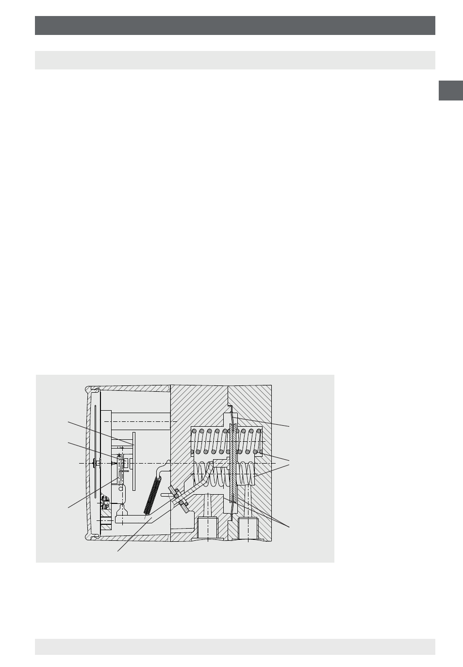
4. Design and function
4.1 Description
4. Design and function
Pressures p
1
and p
2
act on the media chambers ⊕ and ⊖, which are separated by
an elastic diaphragm (1).
The differential pressure (Δp = p
1
- p
2
) leads to an axial deflection of the
diaphragm against the measuring range springs (2).
The deflection, which is proportional to the differential pressure, is transmitted to
the movement (4) in the indicating case via a pressure-tight and low friction rocker
arm (3).
A magnet (5), fixed to the rear of the movement, affects the electromagnetic field
of the HALL sensor. The signal that results from this is converted to a standardised
current output signal by the signal conditioning board (6).
Overpressure safety is provided by metal bolsters (7) resting against the elastic
diaphragm.
14077606.01
⊖
⊕
4.2 Scope of delivery
Cross-check scope of delivery with delivery note.