WIKA D-21-9 User Manual
Page 5
2059064.04 GB/D/F/E 06/2008
8 WIKA Operating instructions/Betriebsanleitung/Mode d'emploi/Instrucciones de servicio D-2X-9
2059064.04 GB/D/F/E 06/2008
9
WIKA Operating instructions/Betriebsanleitung/Mode d'emploi/Instrucciones de servicio D-2X-9
Specifications
Model D-20-9, D-21-9
Pressure ranges
bar
0.25
0.4
0.6
1
1.6
2.5
4
6
10
16
Over pressure safety
bar
2
2
4
5
10
10
17
35
35
80
Burst pressure
bar
2.4
2.4
4.8
6
12
12
20.5
42
42
96
Pressure ranges
bar
25
40
60
100
160
250
400
600
1000
1)
Over pressure safety
bar
50
80
120
200
320
500
800
1200 1500
Burst pressure
bar
96
400
550
800
1000 1200 1700
2)
2400
2)
3000
{Vacuum, gauge pressure, compound range, absolute pressure are available}
1)
Only Model D-20-9.
2)
For model D-21-9: the value specified in the table applies only when sealing is
realised with the sealing ring underneath the hex. Otherwise max. 1500 bar applies.
Materials
Wetted parts
(Other materials see WIKA diaphragm seal program)
Model D-20-9
*)
»
Stainless steel
Model D-21-9
»
Stainless steel {Hastelloy}
O-ring: NBR {FPM/FKM or EPDM}
Case
Stainless steel
Internal transmission fluid
3)
Synthetic oil {Halocarbon oil for oxygen applications}
{Listed by FDA for Food and Beverage}
3)
Not for D-20-9 with pressure ranges > 25 bar
Power supply U
B
U
B
in VDC
10 < U
B
≤ 30
Signal output
CANopen protocol acc. to CiA DS-301 V. 4.02,
Device profile DS-404 V. 1.2
Power input
W
< 0.5 {with galvanic isolation
< 0.7}
Communication services
LSS (CiA DSP 305, Version 1.1.1) Services
Configuration of device address and baud rate
Sync/Async, Node/Lifeguarding, Heartbeat
Filter
Individually programmable filter, to eliminate e. g. resonance frequen-
cies
Connect the instrument to earth via the pressure connection.
Operate the pressure transmitter with a shielded cable and earth the shield at least on
one side of the cable.
Use power supplies which guarantee reliable electrical isolation of the operating
voltage as per IEC/DIN EN 60204-1. Consider also the general requirements for PELV
circuits in accordance with IEC/DIN EN 60204-1.
Ingress protection per IEC 60529 (The ingress protection classes specified only apply
while the pressure transmitter is connected with female connectors that provide the
corresponding ingress protection).
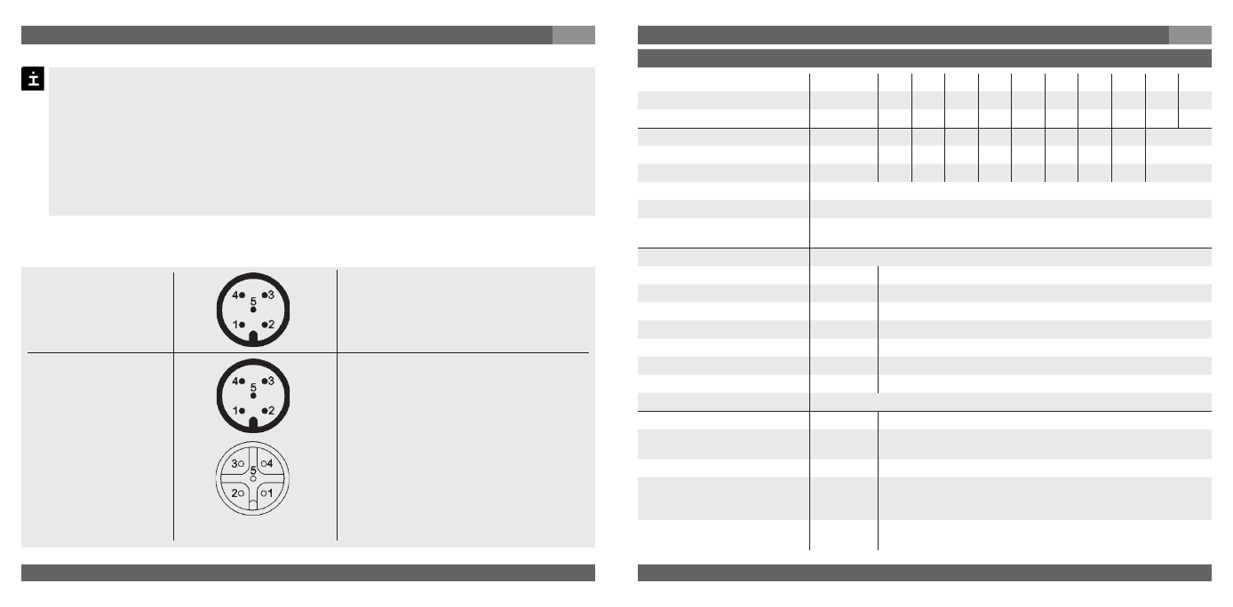
Electrical connection
7. Starting, operation
GB
PIN assignment of connections according to CiA-DR 0-1
With integrated Y-piece
Circular connector
M 12x1, 5 pin, male
Circular connector
M 12x1, 5 pin, female
Circular connector
M 12x1, 5 pin, male
IP 67
Order code: M5
1 – Screen
2 – UB+ (CAN V+)
3 – UB- (CAN GND)
4 – Bus-Signal CAN-High
5 – Bus-Signal CAN-Low
1 – Screen
2 – UB+ (CAN V+)
3 – UB- (CAN GND)
4 – Bus-Signal CAN-High
5 – Bus-Signal CAN-Low
1 – Screen
2 – UB+ (CAN V+)
3 – UB- (CAN GND)
4 – Bus-Signal CAN-High
5 – Bus-Signal CAN-Low
IP 67
Order code: 2M
7. Starting, operation
GB