Table 2, Defining the sv-552 processor/switcher – Kramer Electronics SV-552ALC User Manual
Page 12
KRAMER: SIMPLE CREATIVE TECHNOLOGY
Defining the SV-552 Processor/Switcher
8
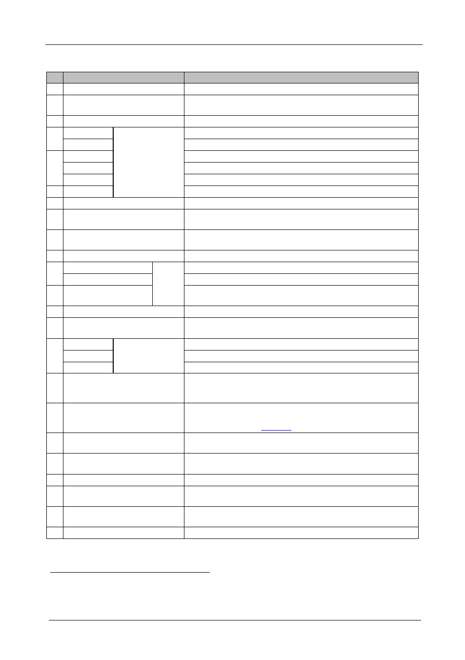
Table 2: SV-552 SummitView™ Processor/Switcher Underside Features
#
Feature
Function
1 POWER LED
Lights when the unit receives power
2 AUTO LED
Lights when the unit is configured to automatically identify and
select an input according to a preconfigured priority
3 LOCK LED
Lights when the front panel buttons are locked
4
VIDEO 1
INPUTS Buttons
(used for testing)
Press to select the video 1 source
VIDEO 2
Press to select the video 2 source
5 PC 1
Press to select the PC 1 source
PC 2
Press to select the PC 2 source
PC 3
Press to select the PC 3 source
6 HDMI
Press to select the HDMI source
7 PROGRAM USB Connector
Program software - for service use only
8 MONITOR OUT Terminal Block
Connect to an external audio amplifier. This is the same as the
audio Line Out but lacks level control
9 LINE OUT Terminal Block
Connect to an external audio amplifier. This is the same as the
Monitor Out but with level control
10 SPKR Terminal Block
Connect to the left and right speakers
11 PHANTOM DIP-switch 1
AUX IN
Configures Aux In for use with a microphone
MIC DIP-switch 2
Turns on Phantom Power 9V on the Aux In connector
12 L, G, R Terminal Block
Connect to an additional audio source or microphone for mixing
with the audio line level input (talk over)
13 IR IN 3.5mm Mini Connector
Connect to an IR receiver
14 OUTPUTS TO PROJECTOR DVI
Connector
Connect to the DVI/HDMI input of the projector
15 PC 1
INPUTS
RJ-45 Connectors
Connect to the PC 1 source
PC 2
Connect to the PC 2 source
PC 3
Connect to the PC 3 source
16 ETHERNET RJ-45 Connector
Connect to a PC running the Site-CNTL software via the network or
Internet for control and configuration of the unit. Default IP settings:
Address 192.168.1.39, port 50000, subnet mask 255.255.255.0
17 K-NET
1
Terminal Block
Connect pin G to the Ground connection; Connect pin B and pin A to
the RS-485, and pin +12V to the power adapter. For details on
connecting K-Net, see
18 TERM DIP-switches
DIP-switches for line termination of the unit (DIP-switch 1 is for
K-Net, DIP-switch 2 is for RS-485)
19 PROJECTOR RS-232 9-pin D-sub
Connector
Connect to the projector for projector control
20 MUTE Terminal Block
Mutes the audio outputs
21 10V VOL Terminal Block
Connect to an external potentiometer on a wall plate
2
to adjust the
volume of the speakers
22 RELAYS Terminal Block
Connect to a room item (such as lighting, screen settings, blinds, and
so on)
23 RS-232 Terminal Block
Connect to the RS-232 connector on any serial controlled device
1 K-Net is a proprietary Kramer protocol for interconnecting Kramer units
2 For example, the RC-63DL