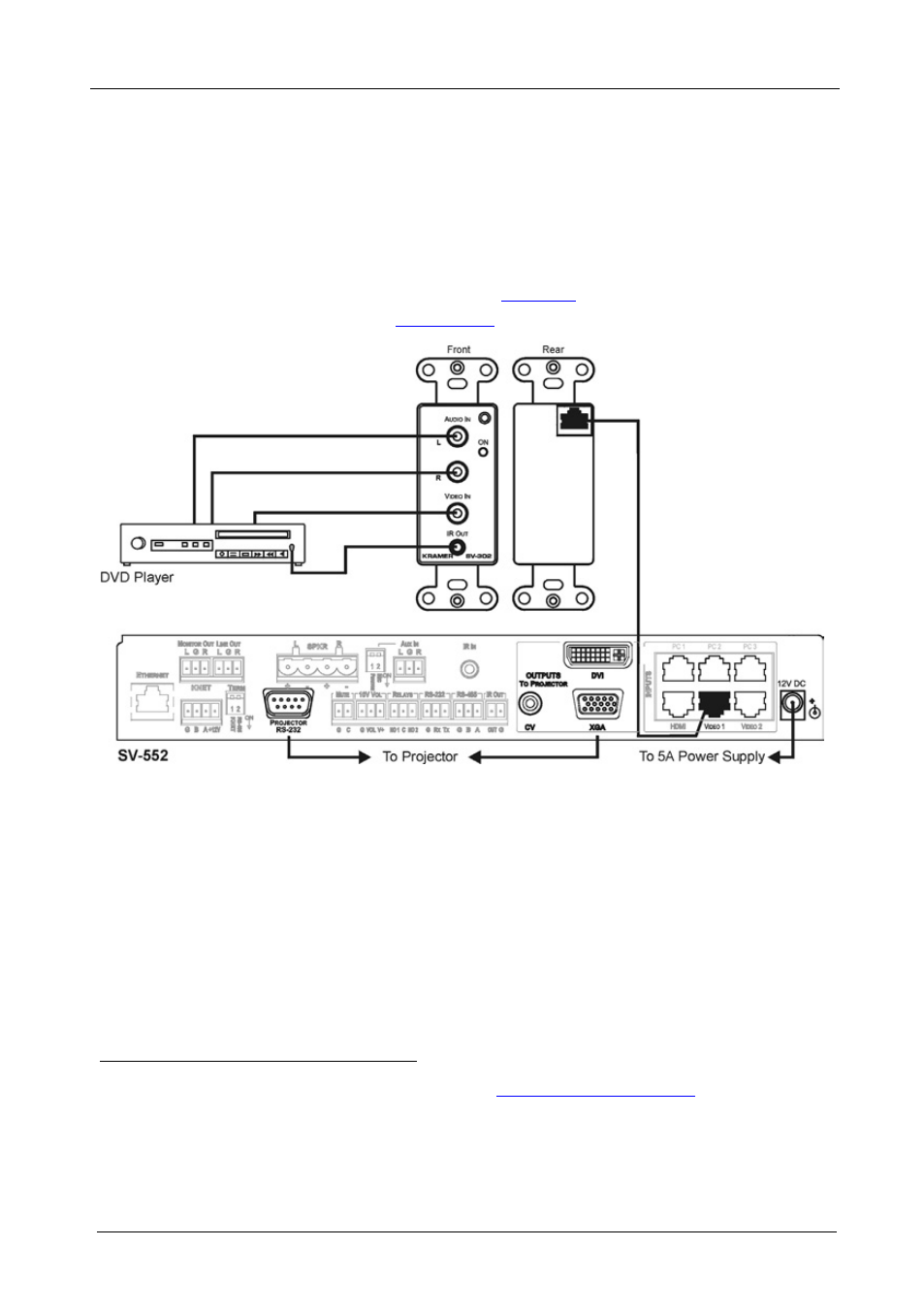
2 connecting the sv-302 wall plate to the sv-552, Connecting the sv-302 wall plate to the sv-552, Figure 8: connecting the sv-302 to the sv-552 – Kramer Electronics SV-552ALC User Manual
Page 30
KRAMER: SIMPLE CREATIVE TECHNOLOGY
Defining and Connecting the Wall Plates
26
Kramer C-GMA/GMA cable (VGA HD15M +Audio connector to VGA
HD15M +Audio connector)
1
.
2. On the rear of the SV-301xl, connect the RJ-45 CAT 5 connector using
either the RJ-45 connector (U.S. version) or terminal block (European
version) to either of the PC 1, PC 2, or PC 3 inputs.
7.3.2
Connecting the SV-302 Wall Plate to the SV-552
To connect the SV-302 as the example in
separate color illustration in
Section 5.1
):
Figure 8: Connecting the SV-302 to the SV-552
1. On the front of the SV-302, connect the:
Composite video source (for example, a DVD
player) to the yellow RCA connector, and to the
unbalanced stereo audio RCA connectors
IR OUT 3.5mm mini connector via an IR Emitter
2
Control cable directly onto the IR sensor window of
the controlled device (for example, a DVD player)
1 Not supplied. The complete list of Kramer cables is available fro
2 The Emitter contains a small infrared LED housed in a miniature, mouse shaped, black plastic shell. It emits visible red light
in addition to IR (infrared) control signals when activated by IR commands sent to it by IR receivers or other controllers. The
Emitter Control Cable comes with a clear adhesive film included on the emitter housing for attachment to the IR window of
the controlled component and pieces of double-sided clear adhesive tape included for replacement purposes