Kramer Electronics VS-88DTP User Manual
Page 11
VS-88DTP - Overview
7
VS
-88D
TP
–
O
ver
vi
ew
7
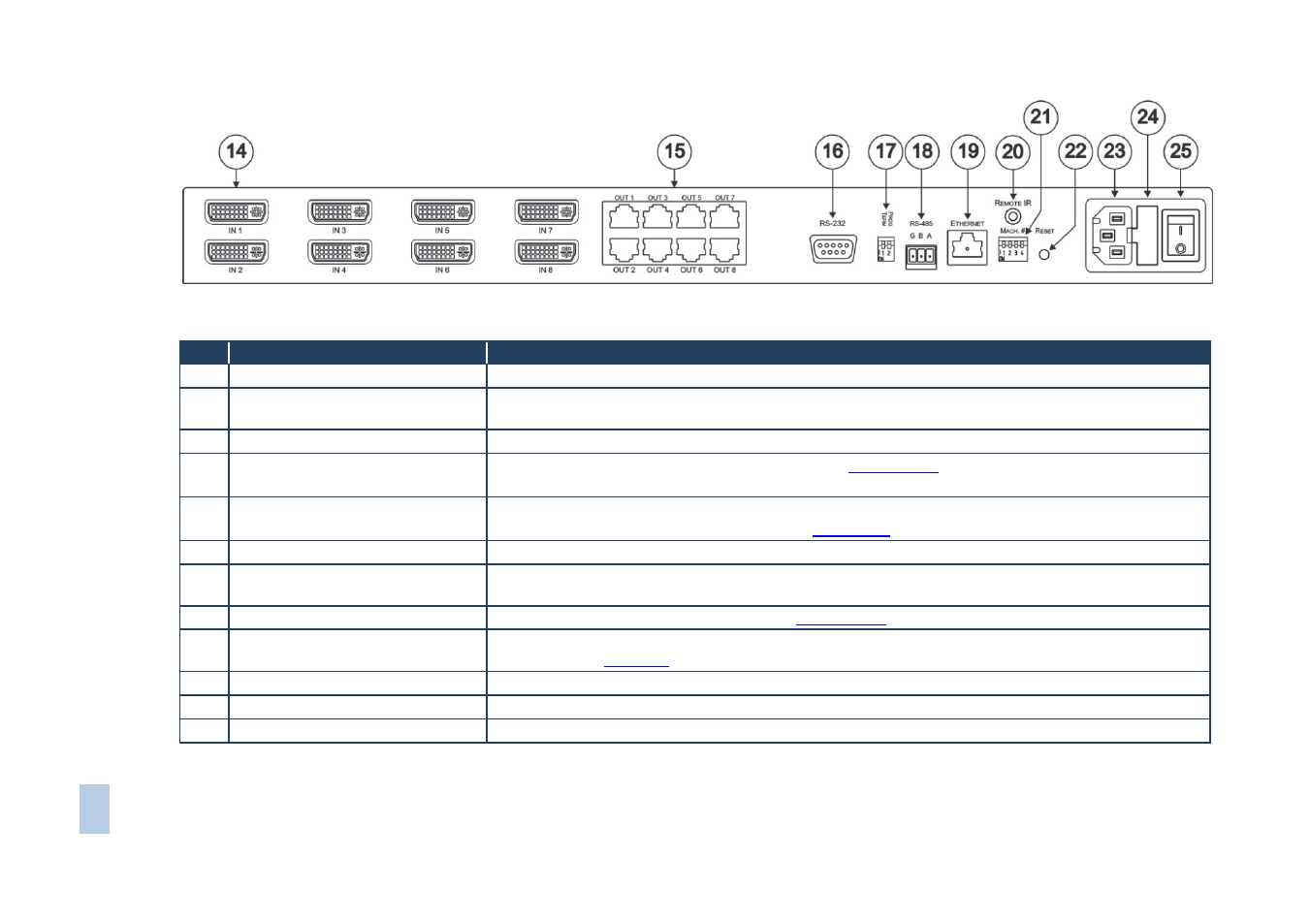
Figure 2: VS-88DTP 8x8 DVI - Twisted Pair Matrix Switcher Rear Panel
#
Feature
Function
14
IN 1 to IN 8 DVI Input Connectors Connect to the DVI sources
15
OUT 1 to OUT 8 RJ-45 TP Output
Connectors
Connect to the TP receivers (for example, PT-572HDCP+ and TP-574)
16
RS-232 9-pin D-sub (F)
Connect to a PC or other serial remote controller
17
PROG TERM 2-way DIP-switch
DIP-switch 1 Sets the RS-485 bus termination (see
5.2.2
DIP-switch 2 Sets the Programming mode. Only for the use of Kramer service personnel. Default = Off
) Up = Off, Down = On. Default = On
18
RS-485 3-pin Terminal Block
Connect to a serial controller or to another
VS-88DTP unit.
Connect G to Ground, B to B, and A to A (see
19
ETHERNET RJ-45 TP Connector
Connect to a PC or LAN for remote control
20
REMOTE IR 3.5mm Mini Jack
Connect to an external IR receiver unit for controlling the device via an IR remote controller (instead of
using the front panel IR receiver)
21
MACH # DIP-Switch
Sets the RS-485 bus machine number (see
22
RESET Button
Press the reset button while turning the device on in order to reset the Ethernet factory default
23
AC Power Receptacle
Connect to the AC mains power supply
24
AC Mains Fuse
AC mains supply protection fuse
25
AC Mains Power Switch
Turns the AC mains power supply to the device on and off