Kramer Electronics VS-44HDxl User Manual
Page 10
Your VS-44HDxl 3G HD/SD-SDI 4x4 Matrix Switcher
7
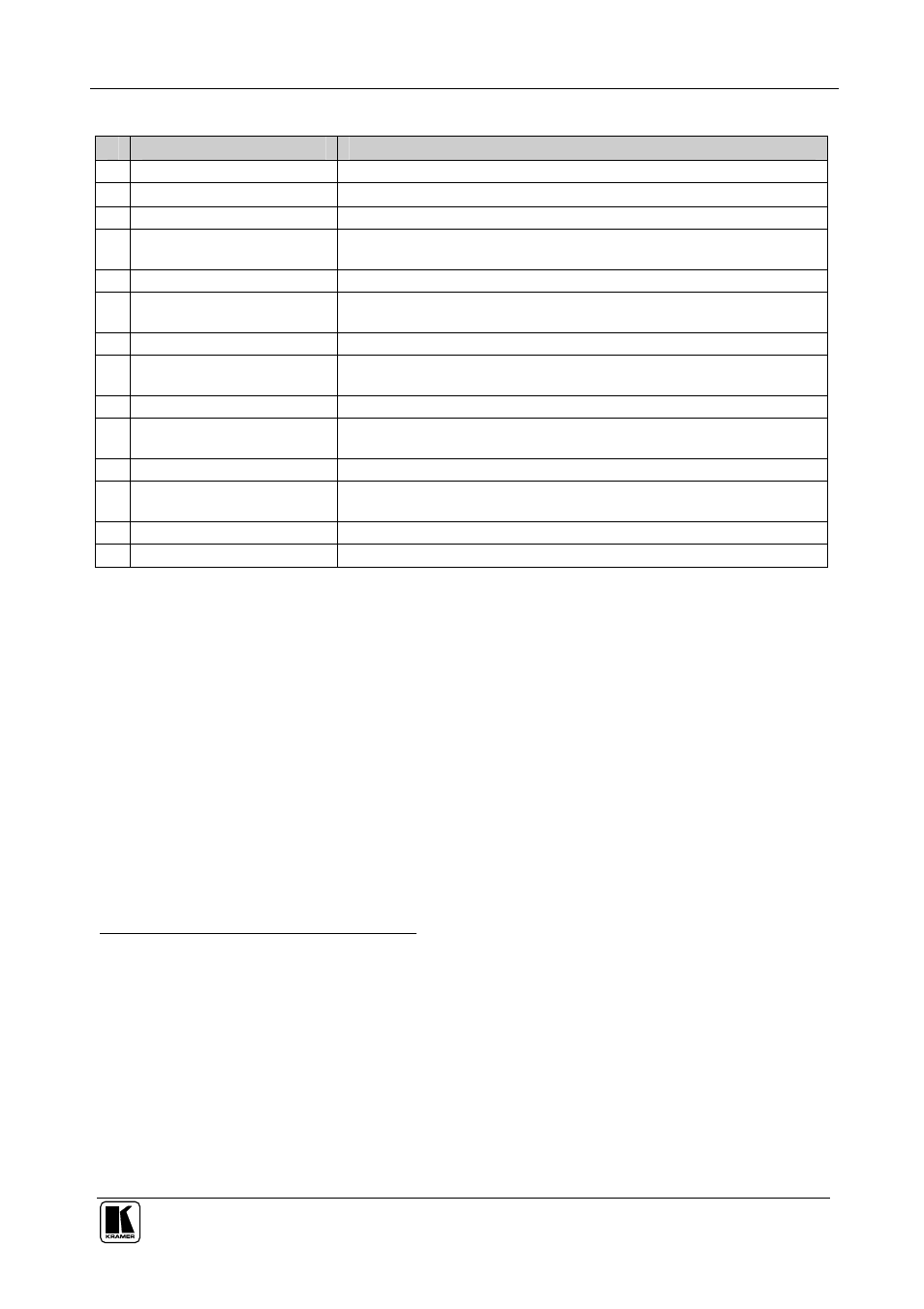
Table 2: Rear Panel VS-44HDxl 3G HD/SD-SDI 4x4 Matrix Switcher
#
Feature
Function
12 GENLOCK BNC Connector Connect to the Genlock source
13 TERM 75 Button
Press to terminate the Genlock source (75 ) or release for looping
1
14 LOOP BNC Connector
Connect to the GENLOCK connector of the next unit in the line
15 DUAL LINK INPUT BNC
Connectors
In the dual-link mode, connect the source to inputs 1 and 2 and/or inputs 3
and 4 (DUAL LINK 1 and/or DUAL LINK 2)
16 INPUT BNC Connectors
Connect to the serial digital video sources (from 1 to 4)
17 DUAL LINK OUTPUT BNC
Connectors
In the dual-link mode, connect the acceptors to outputs 1 and 2 and/or
outputs 3 and 4 (DUAL LINK 1 and/or DUAL LINK 2)
18 OUTPUT BNC Connectors
Connect to the serial digital video acceptors (from 1 to 4)
19 REMOTE Terminal Block
Connector
Connect to contact closure switches (see section 6.9)
20 RS-232 9-pin D-sub Port
Connects to the PC or the Remote Controller
2
21 RS-485 Detachable
Terminal Block Port
Pin G is for the Ground connection
3
; pins B (-) and A (+) are for RS-485
22 SETUP Dipswitches
Dipswitches for setup of the unit
23 REMOTE IR Opening
4
Connects to an external IR receiver unit for controlling the machine via an
IR remote controller (instead of using the front panel IR receiver)
5
24 ETHERNET Connector
Connects to the PC or other Serial Controller through computer networking
25 Power Connector with Fuse AC connector enabling power supply to the unit
4.1 Using the IR Transmitter
You can use the
RC-IR2 IR transmitter to control the machine via the built-in IR
receiver on the front panel or, instead, via an optional external IR receiver
6
. The
external IR receiver can be located 15 meters away from the machine. This
distance can be extended to up to 60 meters when used with three extension
cables
7
.
Before using the external IR receiver, be sure to arrange for your Kramer dealer
to insert the internal IR connection cable
8
with the 3.5mm connector that fits into
the REMOTE IR opening on the rear panel.
Connect the external IR receiver to the REMOTE IR 3.5mm connector.
1 Push in to terminate the input. Release when the input extends to another unit
2 Via a null-modem connection
3 The ground connection is sometimes connected to the shield of the RS-485 cable. In most applications, the ground is not
connected
4 Covered by a cap. The 3.5mm connector at the end of the internal IR connection cable fits through this opening
5 Optional. Can be used instead of the front panel (built-in) IR receiver to remotely control the machine (only if the internal
IR connection cable has been installed)
6 Model: C-A35M/IRR-50
7 Model: C-A35M/A35F-50
8 P/N: 505-70434010-S