Kramer Electronics VS-42HC User Manual
Page 8
Your VS-42HC 4x2 Home Entertainment Matrix Switcher
5
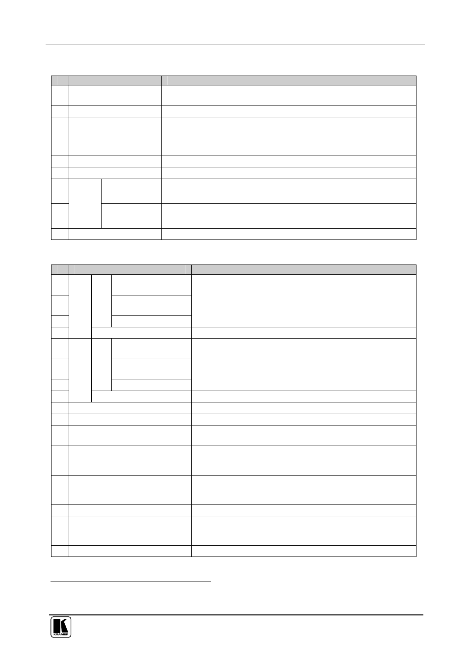
Table 2: Front Panel VS-42HC 4x2 Home Entertainment Matrix Switcher Features
#
Feature
Function
1 IR Receiver
The red LED is illuminated when receiving signals from the infra-red
remote control transmitter
2
POWER
Switch
Illuminated switch for turning the unit ON or OFF
3
DELAY
Button
Toggles the output 2 delay feature between:
On – activate the delay
Set – set the delay time
Off – turn off the delay (see section 8.2)
4
+
Button
Press to increase the audio delay time (and also item 7 in this table)
5
-
Button
Press to decrease the audio delay time (and also item 7 in this table)
6
TO OUTPUT 1
Buttons
Select the input to switch to output 1 (from 1 to 4)
7
IN
P
U
T
S
E
LE
C
TO
R
TO OUTPUT 2
Buttons
Select the input to switch to output 2 (from 1 to 4) (and also items 4 and
5 in this table)
8
LOCK
Button
Disengages/engages the front panel switches
Table 3: Rear Panel VS-42HC 4x2 Home Entertainment Matrix Switcher Features
#
Feature
Function
9
Pb/Cb
RCA
Connectors
10
Pr/Cr
RCA
Connectors
11
C
om
po
ne
nt
Y
RCA Connectors
Connect to the component (Y, Pb/Cb, Pr/Cr) video source
(from IN 1 to IN 4)
12
IN
S/PDIF
Connect to the digital audio source (from IN 1 to IN 4)
13
Pb/Cb
RCA
Connectors
14
Pr/Cr
RCA
Connectors
15
C
om
po
ne
nt
Y
RCA Connectors
Connect to the component (Y, Pb/Cb, Pr/Cr) video acceptor
(OUT 1 and OUT 2)
16
OUT
S/PDIF
Connect to the digital audio acceptor (OUT 1 and OUT 2)
17
OUT 2
TOSLINK Connector
Connect to the digital audio acceptor
1
18
IN 2
TOSLINK Connector
Connect to the digital audio source
1
19
ETHERNET
Connector
Connects to the PC or other Serial Controller through computer
networking LAN
20
SETUP
Dipswitches
Dipswitches for setup of the unit (1, 2, 3 and 4 are for setting
the machine #; 6 and 7 are for selecting the digital audio
source and 8 is for RS 485 Termination)
21
RS-485
Terminal Block Port
Pins B (-) and A (+) are for RS-485 connection. If shielded
cabling is used for RS-485, then the shield may be connected
to Pin G is desired
22
RS-232
DB 9F Port
Connects to the PC or the Remote Controller
23
FLASH Upgr.
Button
Push in
2
for “Program” to upgrade the switcher microcontroller to
the latest Kramer firmware (see
section 9.1.2), or release (the
factory default) for Normal operation
24 Power Connector with Fuse
AC connector enabling power supply to the unit
1 Use an optical cable, such as Sony’s POC-15A (not included in the package)
2 Using a screwdriver if required