Kramer Electronics VS-42HC User Manual
Page 13
KRAMER: SIMPLE CREATIVE TECHNOLOGY
Connecting the VS-42HC
10
6.2 Connecting the Audio Signals
The
VS-42HC 4x2 Home Entertainment Matrix Switcher inputs and outputs
digital audio signals in the following formats:
4 S/PDIF inputs and 2 S/PDIF outputs on RCA connectors (from IN 1 to
IN 4, and from OUT 1 to OUT 2, respectively)
1 TOSLINK input and 1 TOSLINK output for IN 2 and OUT 2
IN 2
OUT 2
IN 3
IN 4
IN 1
DIP 6
DIP 7
OFF
OFF
ON
ON
OUT 1
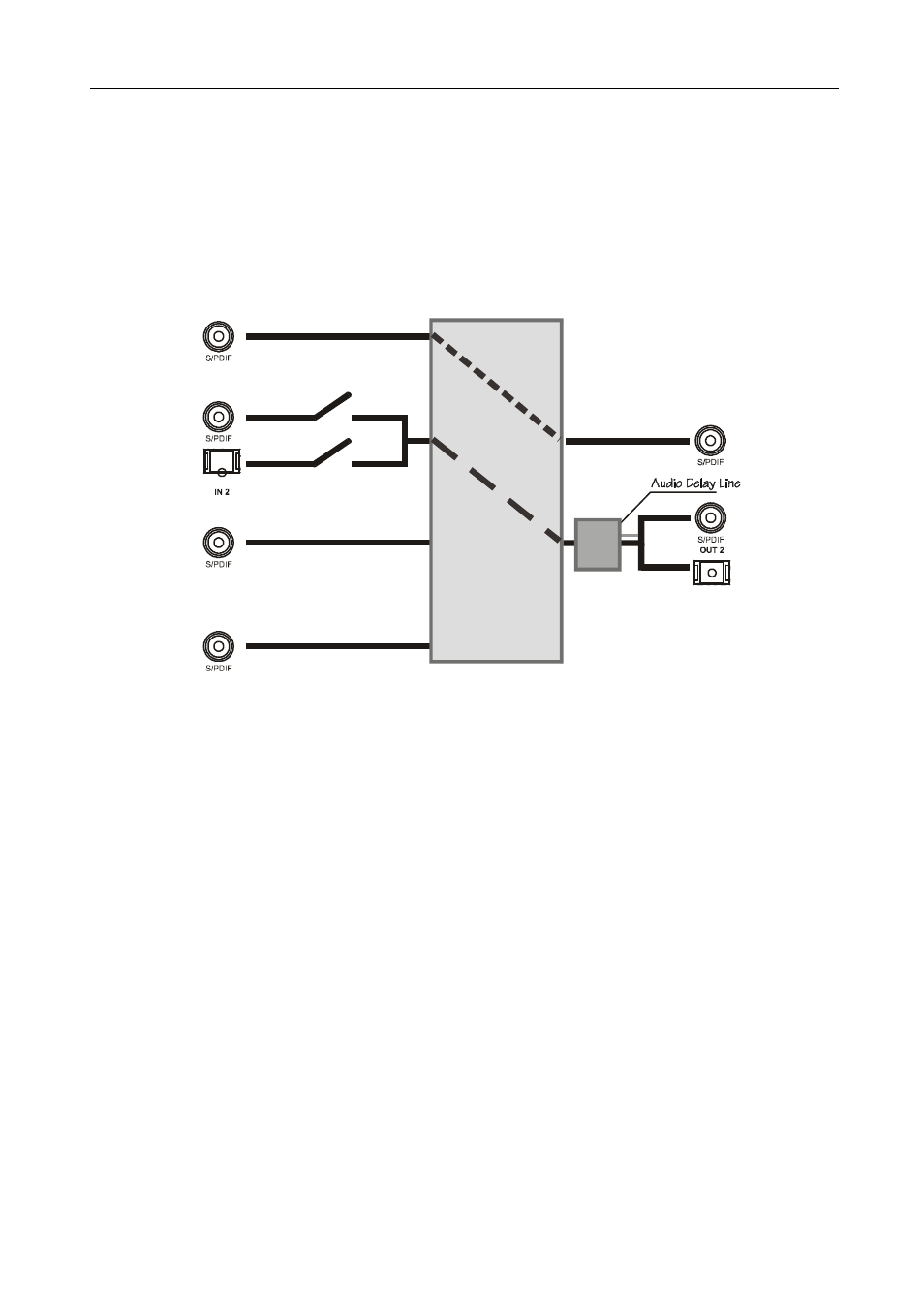
Figure 4: Connecting the VS-42HC Digital Audio Signals
In the example illustrated in Figure 4, IN 1 is switched to OUT 1; IN 3 and
IN 4 are not connected.
The IN 2 digital audio signal can be routed either via the IN 2 S/PDIF
connector, or the IN 2 TOSLINK connector, depending on the setup of
dipswitches 6 and 7 (see section 6.3.2):
To select the S/PDIF connector, set DIP 6 ON
To select the TOSLINK connector, set DIP 7 ON
The digital audio signal on channel 2 is outputted simultaneously to both the
S/PDIF and TOSLINK OUT 2 connectors.
To set the audio delay time, see section 8.2.