Table 9: instruction codes, Kramer protocol 2000, 27 table 9: instruction codes – Kramer Electronics VS-121HC User Manual
Page 30
Kramer Protocol 2000
27
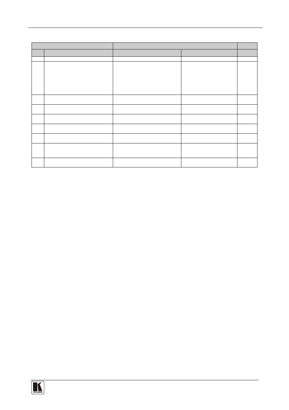
Table 9: Instruction Codes
INSTRUCTION
DEFINITION FOR SPECIFIC INSTRUCTION
NOTE
#
DESCRIPTION
INPUT
OUTPUT
0
RESET VIDEO
0
0
1
1
SWITCH VIDEO
Set equal to video input which is to
be switched
0-12:
0: Disconnect
1–4: CV group
5–8: SV group
9–12: Component group
Set equal to video output
which is to be switched
1
2
5
REQUEST STATUS OF A VIDEO
OUTPUT
Set as SETUP #
0
OUTPUT #
1
3, 4
30
LOCK FRONT PANEL
0: Panel unlocked
1: Panel locked
0
2
31
REQUEST WHETHER PANEL IS
LOCKED
0
0
16
55
REPLY ON
0
0 - Off
1 - On
26
57
SET AUTO SAVE
I3: No save
I4: Autosave
0
12, 2
61
IDENTIFY MACHINE
1: Video machine name
3: Video software version
0: Request first 4 digits
1: Request first suffix
10: Request first prefix
13
62
DEFINE MACHINE
1: Number of inputs
2: Number of outputs
1
14
NOTE 1
When the master switcher is reset, (e.g. when it is turned on), the reset code is sent to the PC. If this code is sent to the
switchers, it will reset according to the present power-down settings.
NOTE 2 – These are bi-directional definitions. That is, if the switcher receives the code, it will perform the instruction; and if
the instruction is performed (due to a keystroke operation on the front panel), then these codes are sent. For example, if the
HEX code
01
85
81
83
was sent from the PC, then the switcher (machine 3) will switch input 5 to output 1. If the user switched input 7 to output 1
via the front panel keypad, then the switcher will send HEX codes:
41
87
81
83
to the PC.
When the PC sends one of the commands in this group to the switcher, then, if the instruction is valid, the switcher replies by
sending to the PC the same four bytes that it was sent (except for the first byte, where the DESTINATION bit is set high).
NOTE 3 – SETUP # 0 is the present setting (Status).
NOTE 4 – The reply to a "REQUEST" instruction is as follows: the same instruction and INPUT codes as were sent are
returned, and the OUTPUT is assigned the value of the requested parameter. The replies to instruction 5 is per the definitions
in instruction 1. For example, if the present status of machine number 5 is input 7, then the reply to the HEX code
05
80
81
85
would be HEX codes
45
80
87
85
NOTE 12 – Under normal conditions, the machine's present status is saved each time a change is made. The "power-down"
save (auto-save) may be disabled using this code. Note that whenever the machine is turned on, the auto-save function is set.
NOTE 13 – This is a request to identify the switcher/s in the system. If the OUTPUT is set as 0, and the INPUT is set as 1,
the machine will send its name. The reply is the decimal value of the INPUT and OUTPUT. For example, for a VS-121HC,
the reply to the request to send the audio machine name would be (HEX codes):
7D
81
95
81 (i.e. 128dec+ 1dec for 2nd byte, and 128dec+ 21dec for 3rd byte).
If the OUTPUT is set as 1, then the ASCII coding of the lettering following the machine’s name is sent. For example, for the
VS-7588YC, the reply to the request to send the first suffix would be (HEX codes):
7D
C8
C3
81 (i.e. 128dec+ ASCII for “H”; 128dec+ ASCII for “C”).
If the request for identification is sent with the INPUT set as 3 or 4, the appropriate machine will send its software version
number. Again, the reply would be the decimal value of the INPUT and OUTPUT - the INPUT representing the number in
front of the decimal point, and the OUTPUT representing the number after it. For example, for version 3.5, the reply to the
request to send the version number would be (HEX codes):
7D
83
85
81 (i.e. 128dec+ 3dec for 2nd byte, 128dec+ 5dec for 3rd byte).