3 operating via the rs-485 port, Operating via the rs-485 port, Figure 3: crossed cable rs-232 connection – Kramer Electronics VS-121HC User Manual
Page 13: Figure 3
KRAMER: SIMPLE CREATIVE TECHNOLOGY
Operating the VS-121HC Switcher/Transcoder
10
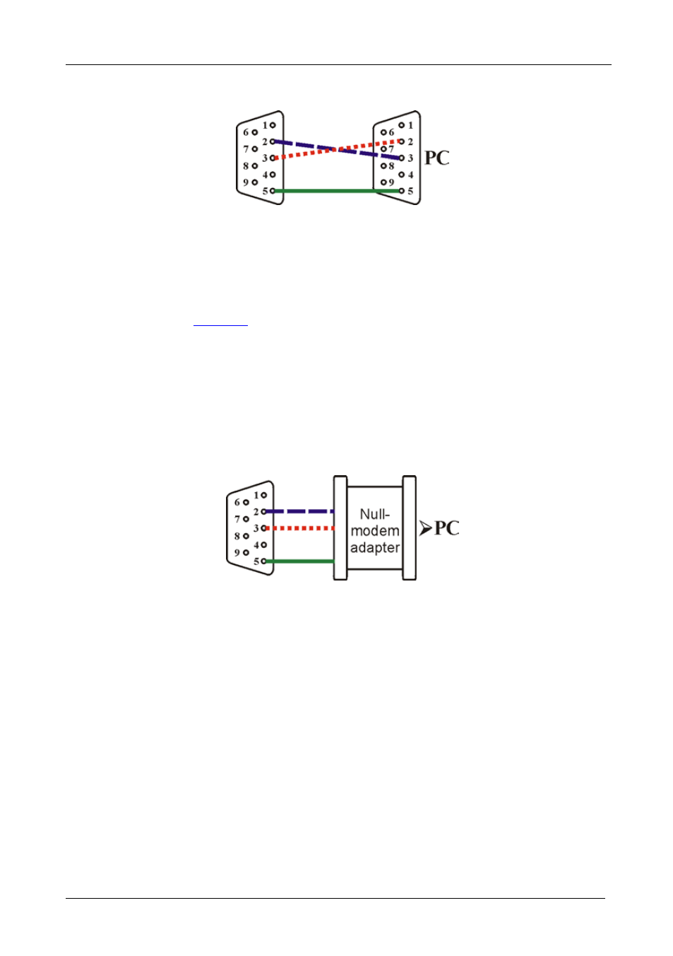
Note: There is no need to connect any other pins.
Figure 3: Crossed Cable RS-232 Connection
Hardware flow control is not required for this unit. In the rare case where a
controller requires hardware flow control, short pin 1 to 7 and 8, and pin 4
to 6 on the controller side.
Method B (
)—Connect the RS-232 9-pin D-sub port on the unit via
a straight (flat) cable to the null-modem adapter, and connect the null-
modem adapter to the RS-232 9-pin D-sub port on the PC. The straight
cable usually contains all nine wires for a full connection of the D-sub
connector. Because the null-modem adapter (which already includes the
flow control jumpering described in Method A above) only requires pins 2,
3 and 5 to be connected, you are free to decide whether to connect only
these 3 pins or all 9 pins.
Figure 4: Straight Cable RS-232 Connection with a Null Modem Adapter
7.3
Operating via the RS-485 Port
You can operate the VS-121HC via the RS-485 port from a distance of up
to 1200 meters (3900ft) using any device equipped with an RS-485 port (for
example, a PC). For successful communication, you must set the RS-485
machine number and bus termination.
To connect a device with a RS-485 port to the VS-121HC:
• Connect the TxD+ pin on the RS-485 port of the PC to the A (+) pin on
the RS-485 port on the rear panel of the VS-121HC
• Connect the TxD- pin on the RS-485 port of the PC to the B (-) pin on
the RS-485 port on the rear panel of the VS-121HC
• If shielded twisted pair cable is used, the shield may be connected to
the G (ground) pin on the unit