Kramer Electronics VP-81SIDN User Manual
Page 11
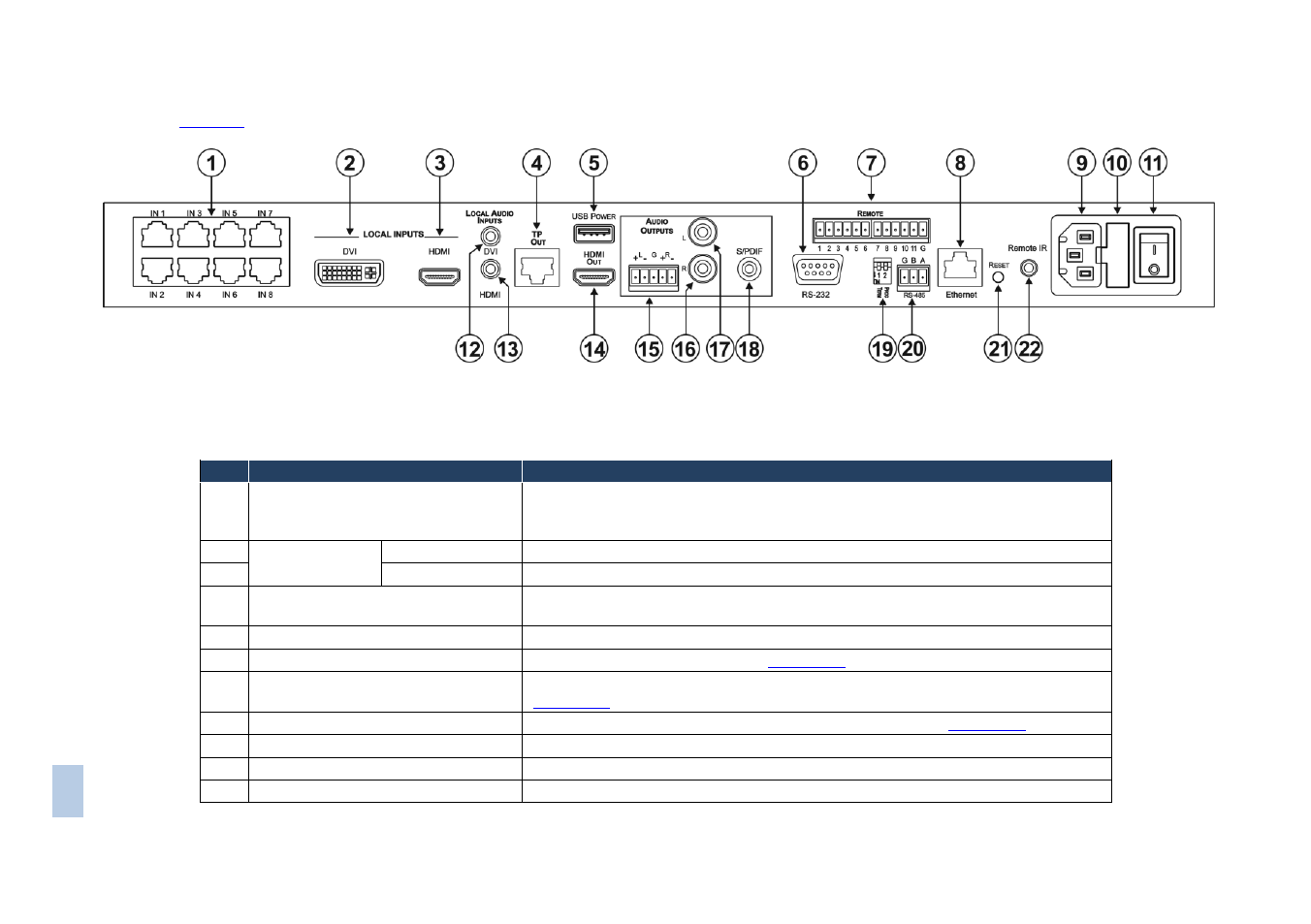
defines the rear panel of the VP-81SIDN.
Figure 2: VP-81SIDN 8x1 Digital Step-In Switcher Rear Panel
#
Feature
Function
1
TP Input RJ-45 Connectors IN 1 to
IN 8
Connect to the remote TP sources (1 to 8) using CAT 6 or higher specification
cable. These may be step-in panels (for example, SID-DP) or TP transmitters (for
example, the PT-571 or TP-573)
2
LOCAL
INPUTS
DVI
Connect to the local DVI source
3
HDMI
Connect to the local HDMI source
4
TP OUT RJ-45 Connector
Connect to the remote TP receiver, for example, PT-572+, using CAT 6 or higher
specification cable (maximum 50m, 164ft)
5
USB POWER Connector
Connect any device requiring USB power, (for example, the Kramer KW-11T)
6
RS-232 9-pin D-sub Port (F)
Connect to a serial controller (see
Section
7
REMOTE 12-way Terminal Block
Connect to remote contact closure input and output selection switches (see
Section
8
ETHERNET RJ-45 Connector
Connect to a PC or LAN for remote control via Ethernet (see
Section
9
AC Mains Power Socket
Connect to the AC mains power
10
AC Mains Fuse
AC mains supply protection fuse
11
AC Mains Power Switch
Turns the AC mains power supply to the device on and off
VP
-8
1
S
IDN
–
De
fin
in
g
t
h
e
VP
-8
1
S
ID
N 8
x
1
Di
g
it
a
l
S
te
p
-In
S
wi
tc
h
e
r
7