Table 2, Your vp-27 presentation switcher – Kramer Electronics VP-27 User Manual
Page 9
KRAMER: SIMPLE CREATIVE TECHNOLOGY
Your VP-27 Presentation Switcher
6
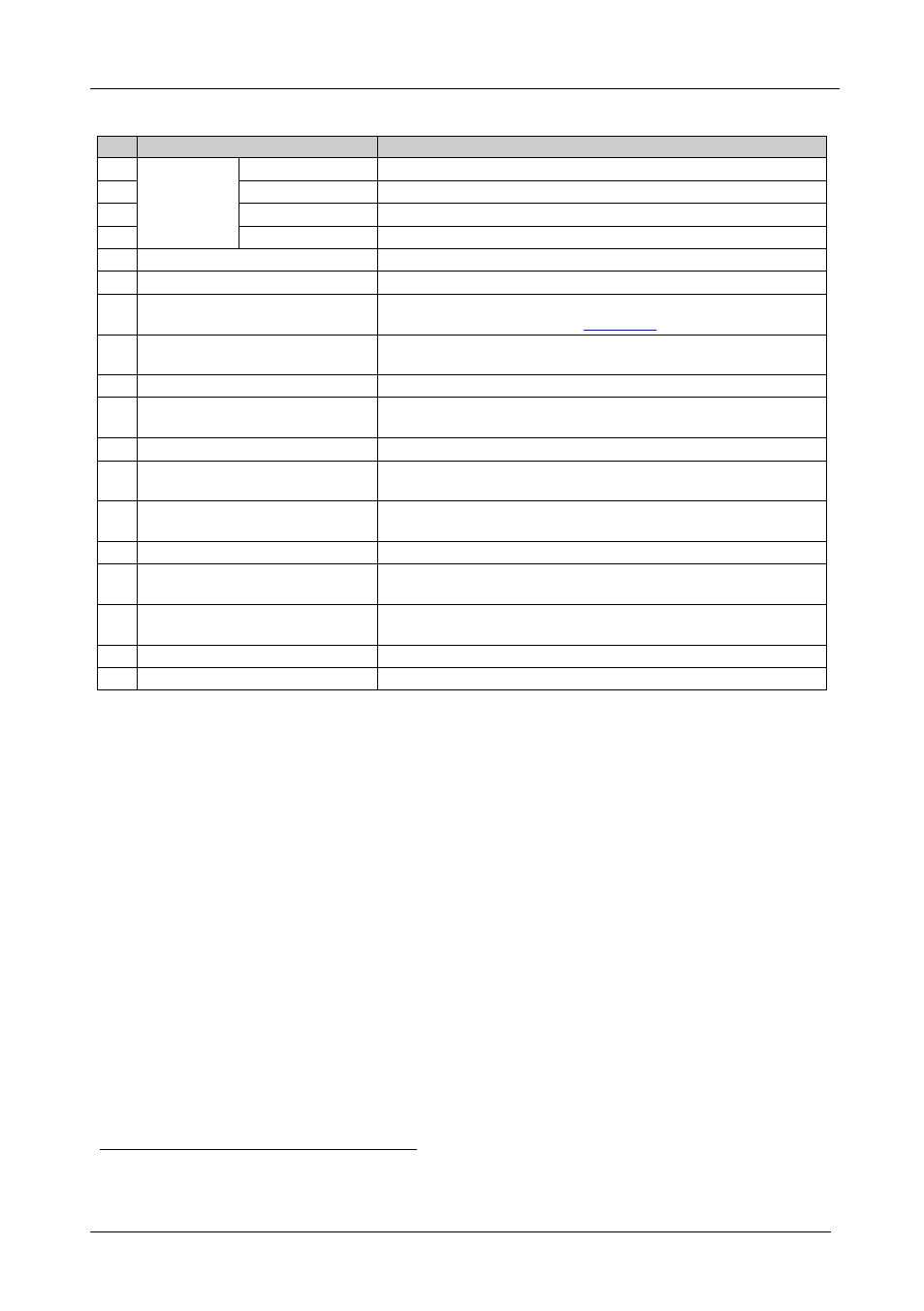
Table 2: Rear Panel VP-27 Presentation Switcher Features
#
Feature
Function
18
Video
Connectors
Y/C IN 4-pin
Connect to the s-Video sources
19
CV IN RCA
Connect to the composite video sources
20
Y/C OUT 4-pin
Connect to the s-Video acceptor
21
CV OUT RCA
Connect to the composite video acceptor
22
PC IN 15-pin HD Connectors
Connect to the VGA/UXGA video sources
23
PC OUT 15-pin HD Connector
Connect to the VGA/UXGA video acceptor
24
DIP-switches
DIP-switches for setup of the unit (DIP 1 and 4 are not used; DIP
2 PROG
, DIP 3 MIC DC; see
Section
25
RS-232 (Tx, Rx, G) Terminal
Block Connector
Connects to the PC or the Remote Controller
26
PC AUDIO IN 3.5mm Mini Plugs
Connect to the s-Video unbalanced audio sources
27
PC AUDIO OUT 3.5mm Mini
Plug
Connect to the PC unbalanced stereo audio acceptor (for the PC
video)
28
MIC 6.3mm Phone Jack Connector Connect to the microphone
29
CV AUDIO IN RCA Connectors
Connect to the unbalanced audio sources
30
of the composite
video
CV AUDIO OUT RCA
Connectors (L and R)
Connect to the composite video unbalanced audio acceptor (for
the composite video)
31
Y/C AUDIO IN RCA Connectors
Connect to the s-Video unbalanced audio sources
32
Y/C AUDIO RCA Connectors (L
and R)
Connects to the s-Video unbalanced audio acceptor (for the
s-Video)
33
MASTER OUT RCA Connectors
(L and R)
Connect the master unbalanced audio channel acceptor
34
Power Connector with Fuse
AC connector enabling power supply to the unit
35
POWER Switch
Illuminated switch for turning the unit ON or OFF
1 Always set to OFF (for factory use)
2 From 1 to 4