2 the audio gain control ascii tables, 13 kramer protocol, 1 protocol output definitions – Kramer Electronics VP-27 User Manual
Page 22: 2 switching protocols, The audio gain control ascii tables, Kramer protocol, Protocol output definitions, Switching protocols
Kramer Protocol
19
19
12.2
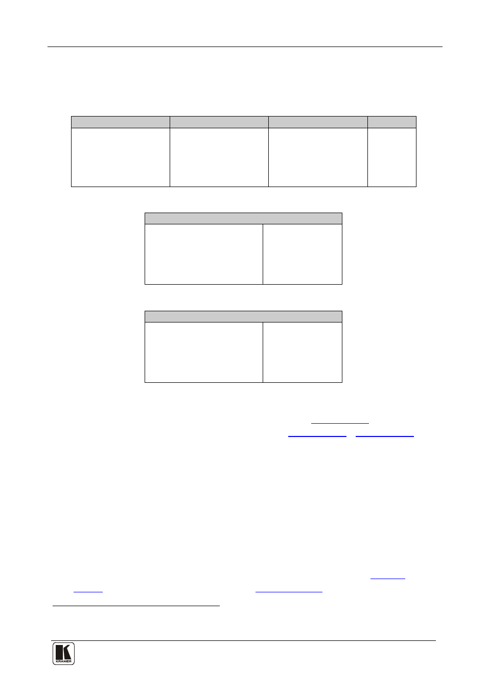
The Audio Gain Control ASCII Tables
The following tables describe the audio gain controls.
Table 12: Set the Audio Gain Control for the Groups
CV Group Input
Y/C Group Input
PC Group Input
Notes
# AUD-LVL 1,1,0
# AUD-LVL 1,2,0
# AUD-LVL 1,3,0
Mute
…
…
…
# AUD-LVL 1,1,227
# AUD-LVL 1,2,227
# AUD-LVL 1,3,227
…
…
…
# AUD-LVL 1,1,255
# AUD-LVL 1,2,255
# AUD-LVL 1,3,255
Table 13: Set the Audio Output Gain Control for the Microphone
Audio Gain Control for Microphone
# AUD-LVL 2,4,0
Mute
…
# AUD-LVL 2,4,215
0dB (1:1)
…
# AUD-LVL 2,4,255
Maximum
Table 14: Set the Audio Output Gain Control for the Master Audio
Audio Gain Control for Master Out
# AUD-LVL 2,0,0
Mute
…
# AUD-LVL 2,0,227
0dB (1:1)
…
# AUD-LVL 2,0,255
Maximum
13 Kramer Protocol
By default, the VP-27 is set to protocol
3000 (see
) but is also
compatible with Kramer’s Protocol 2000 (see
Section 13.4
).
Section 13.2
describes how to switch between protocol 3000 and protocol 2000.
13.1
Protocol Output Definitions
The protocol output definitions are: Video (CV) group defined as output 1,
Video (YC) group defined as output 2, Video (PC) group defined as output 3,
and Master Audio Selector defined as output 0.
13.2
Switching Protocols
You can switch protocols either via the front panel buttons (see
Section
) or the protocol commands (see
Section 13.2.2
1 You can download our user-friendly “Software for Calculating Hex Codes for Protocol 2000” from the technical support
section on our Web site at: http://www.kramerelectronics.com