Figure 2 – Kramer Electronics VP-1608 User Manual
Page 10
6
VP-1608 - Overview
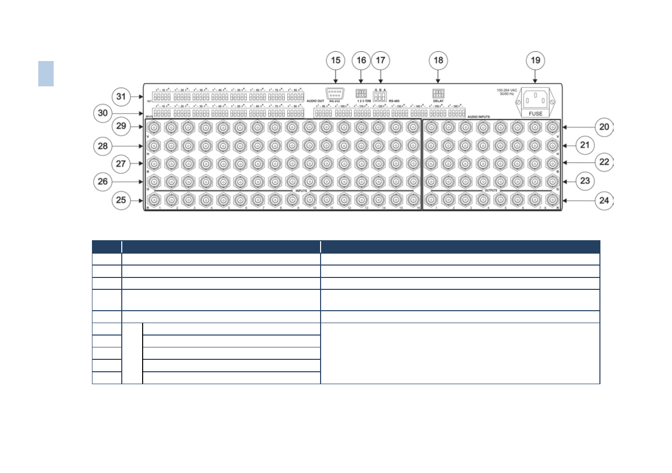
Figure 2: VP-1608 16x8 RGBHV/Balanced Audio Matrix Rear Panel
#
Feature
Function
15
RS-232
9-pin D-sub (F) Connector
Connects to the PC or other Serial Controller
16
Setup DIP-switches
DIPS 1, 2, and 3 for setup of the Machine #; DIP 4 for RS-485 termination
17
RS-485
Connector
RS-485 port on detachable terminal block
18
DELAY
DIP-switches
DIP-switches for setup of the delay time ranging from 0sec to 3.5sec (in
increments of 0.5sec)
19
Power Connector with Fuse
AC connector enabling power supply to the unit
20
V
ideo
O
ut
pu
ts
V
(Vertical Sync) OUTPUT BNC Connectors
Connect to the RGBHV video acceptors (1 to 8)
For RGBS applications, one of the sync channels (H or V) may be used for the S
channel
21
H
(Horizontal Sync) OUTPUT BNC Connectors
22
B OUTPUT
BNC Connectors
23
G OUTPUT
BNC Connectors
24
R OUTPUT
BNC Connectors
6
VP
-16
08
–
O
ver
v
iew
- VM-216H (25 pages)
- VM-28H (23 pages)
- VM-22H (12 pages)
- VM-24H (23 pages)
- VM-24HC (21 pages)
- VM-24HD (10 pages)
- VM-24HDCP (19 pages)
- VM-42 (8 pages)
- VP-222K (10 pages)
- VP-242 (8 pages)
- VP-32K (13 pages)
- VS-202YC (23 pages)
- 4x1S (15 pages)
- 4x1V (12 pages)
- 6241HDxl (10 pages)
- 6241N (10 pages)
- 6502 (12 pages)
- PT-201VGA (8 pages)
- TailorMade (21 pages)
- TailorMade (22 pages)
- VP-1201 (50 pages)
- VP-12x8 (34 pages)
- VS-88SDI (42 pages)
- VP-321xl (37 pages)
- VP-16x18AK (60 pages)
- VP-201xl (8 pages)
- VP-211K (15 pages)
- VP-27 (32 pages)
- VS-88HDxl (43 pages)
- VS-66HN (25 pages)
- VP-28 (42 pages)
- VP-2x2 (17 pages)
- VP-31 (25 pages)
- VP-311DVI (20 pages)
- VS-88HD (44 pages)
- VS-88HD (21 pages)
- VP-31KSi (16 pages)
- VP-81KSi (51 pages)
- VP-31KSi (48 pages)
- VP-41 (8 pages)
- VP-411DS (22 pages)
- VS-81HDxl (25 pages)
- VP-4x1CS (39 pages)
- VP-4x4K (61 pages)