Festo Направляющая FDG User Manual
Page 17
FDG−...
Festo FDG−... 0612a English
17
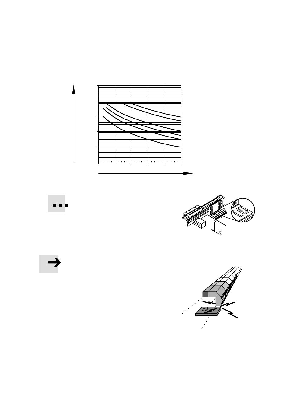
500
1000
1500
2000
2500
3000
FDG–25
FDG–32
FDG–40
FDG–18
100
1000
10000
10
1
l [mm]
F
[N
]
100000
FDG–50
FDG–63
Fig. 6
Fasten the axis fastening kits or centre supĆ
ports on the FDG−... as shown in the adjacent
diagram.
If necessary, sliding blocks can be used as a
fastening device in the profile grooves.
If the FDG is used in conjunction with a drive axis type DGE−... or DGP(L)−...:
S
Set the distances between supports as shown for the FDG−... .
In this way you will avoid distortion as a
result of sagging at irregular intervals.
When fitting the fastening elements:
S
Make sure that the axis fastening kit or
the cente supports are placed outside the
positioning range of the slide and cannot
collide with it.
УУУ
УУУ
УУУ
Fig. 7: Q = Side play
Fig. 8