RMS Technologies IMCE23 INTERGRATED MOTOR+CONTROLLER +DRIVER+ENCOD User Manual
Page 5
1. FEATURES
• Operates from +12V to 40V
• Single 2 wire bus linking up to 16 drive/controls ( on RS485 bus)
• 3.0 Amp Peak Chopper (PWM) Driver (2.14 A/Ph)
• Full step, 1/2, 1/4, 1/8, 1/16, 1/32, 1/64, 1/128, 1/256 step resolution
• Stand alone operation with no connection to a PC
• Execution Halt pending switch push button
• Pre-wired internally for Opto Switch inputs
• Homes to an Opto or Switch closure with a single command
• Fully programmable ramps and speeds
• Four digital I/O and two fixed input channels
• Switch selectable address
• Software selectable "Move" and "Hold" currents
• Two inputs can be used for left and right limit switches
• Option to use unit as a driver only and accept TTL step pulses
• Takes in single-ended optical encoder input for position correction
• Hold Current automatically selected upon move completion
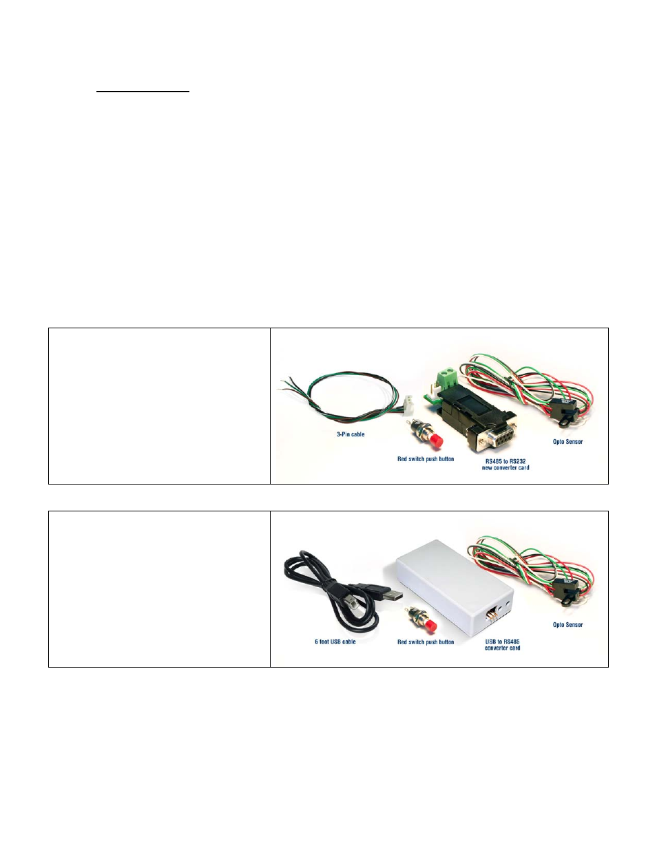
Designer’s Kit with RS232 communication
Here is the list of components if you
have purchased the optional
Designer’s Kit:
• RS485 to RS232 converter card
• A switch push button
• Opto Sensor
• 3-Pin cable (optional usage)
RMS part number: KIT-RS232
Designer’s Kit with USB communication
Here is the list of components if you
have purchased the optional
Designer’s Kit:
• USB to RS232 converter card
• A switch push button
• Opto Sensor
• A USB 6 foot long cable
Lin part number: KIT-USB
R356’s Encoder Option
A single-ended optical encoder must be installed on your motor in order to have
encoder feedback. Position correction mode can be turned on such that it will
continually send step pulses until the true desired position and actual position equals
each other. The option of simply sending an error report is also possible. The R356
must first be set up to work with the encoder by understanding the CPR and
calculating an encoder ratio. See the Appendix of this user manual.