Half- stepping current wave form – RMS Technologies IMCE23 INTERGRATED MOTOR+CONTROLLER +DRIVER+ENCOD User Manual
Page 22
R356 Controller & Driver
Page 22
Version 1.06
RMS Technologies
2/17/2010
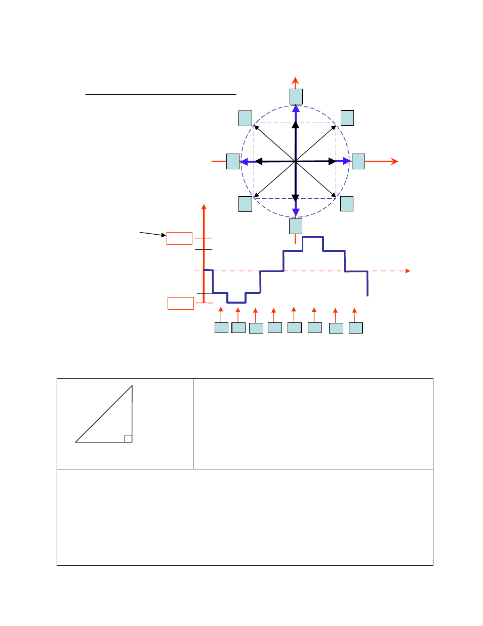
Beginning at position 1, Phase A receives negative current, and Phase B receives
positive current. Let’s assume it is at coordinate (-1, 1).
The position versus time graph just above, plots only the A Phase, following the eight
different steps the motor will make. Current is changing with each position. Recall
that a negative in electronics simply means reverse direction of current flow.
Take a look at position #7. If we were to draw the arrow
at position 7 as the hypotenuse of a triangle, it would
look like the triangle to our left. Recall from geometry a
90°-45°-45° triangle is a 1-1-√2 combination. The √2,
or 1.4 value is also the radius of the dotted circle shown
above. Therefore, during certain steps, Phases A or B will
receive 1.4 Amps of current. But the average, or RMS
current throughout these 8 steps is only 1.0 Amps. RMS
and Amps/Phase is the same meaning.
The 1.4A along this hypotenuse is also known as the 2-Phase On position, since both A and
B Phases are “On” and receive current. It is also known as the peak current.
As we see the waveform that’s plotted for the A Phase, the highest value on the curve is
known as the peak value.
Motors have a rated current, or average RMS value since in operation, the current is
continuously changing. The most logical way to describe a rating is to take an average, or
RMS (root means squared) value. But drivers understand current in terms of peak current,
therefore the conversion is: Amps/Phase x 1.4 = Amps Peak
1.41 AMP
1 AMP
1 AMP
(√2)
1
3
7
5
1
2
3
4
100%
100%
0%
HALF- STEPPING
Current Wave Form
PHASE A
Current
POSITION
PHASE B
PHASE A
2
4
8
6
5
6
7
8
141%
141%
time
Peak current
(1.4 times Amps/Ph)
Average, or RMS
Is only 1 Amp/Ph