RMS Technologies IMCE23 INTERGRATED MOTOR+CONTROLLER +DRIVER+ENCOD User Manual
Page 18
R356 Controller & Driver
Page 18
Version 1.06
RMS Technologies
2/17/2010
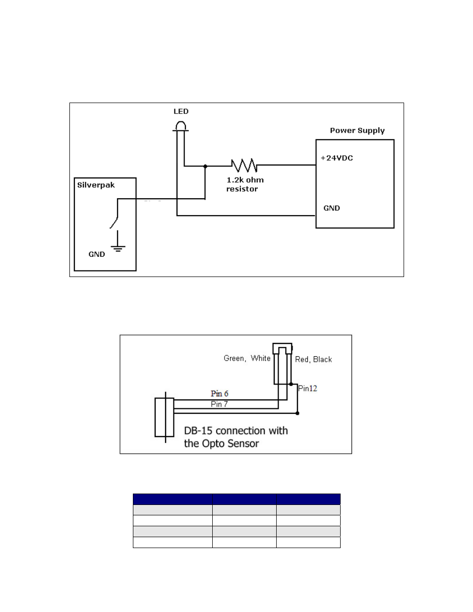
LED or other output
The two I/O lines, pins 2 & 10, can drive an external device such as solenoids, LED’s,
or switches. The bidirectional I/O’s are switches to ground internally, and therefore
need to be connected to the +V of the power supply. Below is a recommended
connection for lighting an LED with 20 mAmps:
Upon entering command /1J0R, both pins 2 & 10 will output 1 Amps. The 1.2k ohm
resistor will limit the current to 20 mAmps into the LED. Select any ohm value to
limit your current based on the device that is connected to the output. I/O’s are
24VDC tolerant.
Optical Sensor
Figure 11: Opto Sensor Connection Schematic
Use the following table to solder the corresponding wires.
Optical Sensor
DB15 Cable
Pin #
Green Æ
Green/white
12
Black Æ Green/white 12
Red Æ
Yellow/white
6
White Æ Orange/white 7
Pin 2
or 10
output