Mittler Bros Machine & Tool 3100-100 Universal Tool Stand User Manual
Assembly instructions
Division of Mittler Corp.
P.O. Box 110 Foristell, Missouri 63348
10 Cooperative Way Wright City, MO 63390
(636) 745-7757
Fax: (636) 745-2874
\\Mbserver01\Engineering\Product\Product Documentation\3100 Universal Tool Stand\Universal Stand Assm. Instructions.doc Rev1 4-
17-2007
3100-100 Universal Tool Stand
Assembly Instructions
Kit Includes:
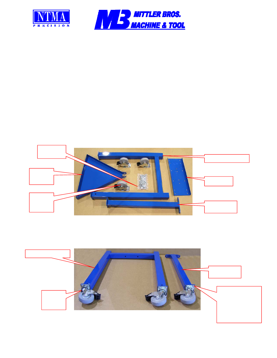
1 ea. Rear “H” frame
1 ea. Front Leg
1 ea. Top Tray
1 ea. Bottom Tray
18 ea. 5/16-18 x 1” Bolts
2 ea. 5/16” -18 x3” Bolts
20 ea. 5/16” Lock washers
20 ea. 5/16” Nuts
16 ea. 5/16” Flat Washer
3 ea. Swivel Casters, Locking
3 ea. 3/8-16 x 3” Bolts
3 ea. 3/8” Nuts
3 ea. 3/8” Lock washers
6 ea. 3/8” Flat washers
1ea. Instruction Sheet
1.
Un-package the contents and verify that nothing is damaged or missing.
2.
Lay the “H” Frame down like shown below. Attach the casters using the 5/16” x 1” bolts, lock washers & nuts. Bolt the
remaining caster to the bottom of the front leg as shown. Be sure bolt are installed from the caster side.
3ea
Swivel
Casters
Check
Hardware
Bottom
Tray
Top Tray
Rear “H” Frame
Front Leg
Rear “H” Frame
3ea
Swivel
Casters
Front Leg
Use 5/16” x 1”
bolts, lock
washers & nuts.
Bolt Heads Must
be on Caster
Side