Edsal 1UFE9 User Manual
Page 3
Assembly Instructions
Assembly Instructions
Assembly Instructions
-
-
-
Page 3
Page 3
Page 3
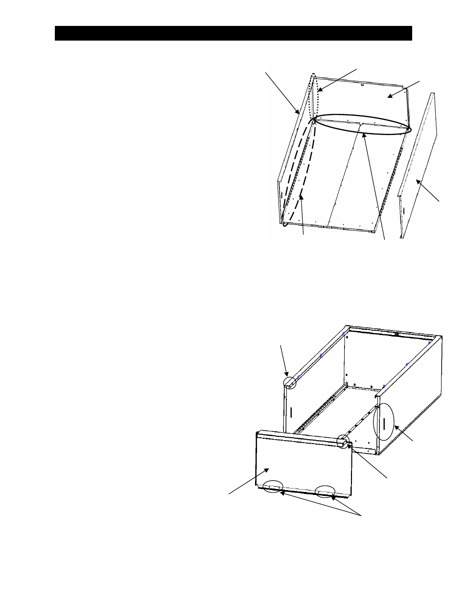
Step 2 - Sides & Top Assembly
First step is to identify the right side panel and the left
side panel. After you have determined the left from the
right panel, place the left side panel with the hinges fac-
ing up toward you under the back assembly making sure
the holes of the side panel flange align with the holes of
the back assembly. After assuring the correct side is
aligned to the back assembly, use the 10-24 x 3/8”
screws and nuts to fasten the side panel to the back as-
sembly. Next take the top and place it into position un-
der the top flanges of the back assembly and the left
hand side panel. Using four (4) 10-24 x 3/8” screws and
nuts for fastening the back of the top, and two (2) 10-24
x 3/8” screws and nuts for fastening the front of the top,
align the screw holes of the top with the screw holes
from the left hand side top flange, and the back assem-
bly top flanges and fasten appropriately (see figure 2 for
screw locations). Now install the right side panel using
the same process as outlined above.
Figure 2 - Sides & Top Assembly
Step 3 - Bottom Assembly
The back, side, and top assembly is ready for the bot-
tom. Holding the bottom from the largest formed side
(front), place the bottom onto the inside of the back, side,
and top assembly. The rear flange of the bottom will
align with the screw holes on the back assembly, and the
sides of the bottom will engage into slots located on the
left and right hand side panels (see figure 3 for refer-
ence). Once all tabs have been properly engaged, and
all the screw holes align, move the front of the bottom
into position so that the screw holes align with the front
of the left and right side panels (use a small tipped screw
driver to assist in aligning the holes if necessary). Using
four (4) of the 10-24 x 3/8” screws and nuts, attach the
back flange of the bottom to the back assembly, and us-
ing four (4) of the 10-24 3/8” screws and nuts attach the
front of the bottom to the side panels (see figure 3 for
screw locations).
Figure 3 - Bottom Assembly
Figure 3 - Top Assem-
Screw Locations
for Top to Side
Screw Locations
for Side to Back
Screw Locations for Back to Top
Left Side
Right Side
Top
Screw Locations
For bottom to sides
(opposite side also)
Screw Locations
For bottom to sides
(opposite side also)
Screw Locations
For bottom to back
Tab Location
For bottom to sides
(opposite side also)
Bottom