Suction and discharge piping checklist, Install a partially-assembled pump – Goulds Pumps VIC - IOM User Manual
Page 20
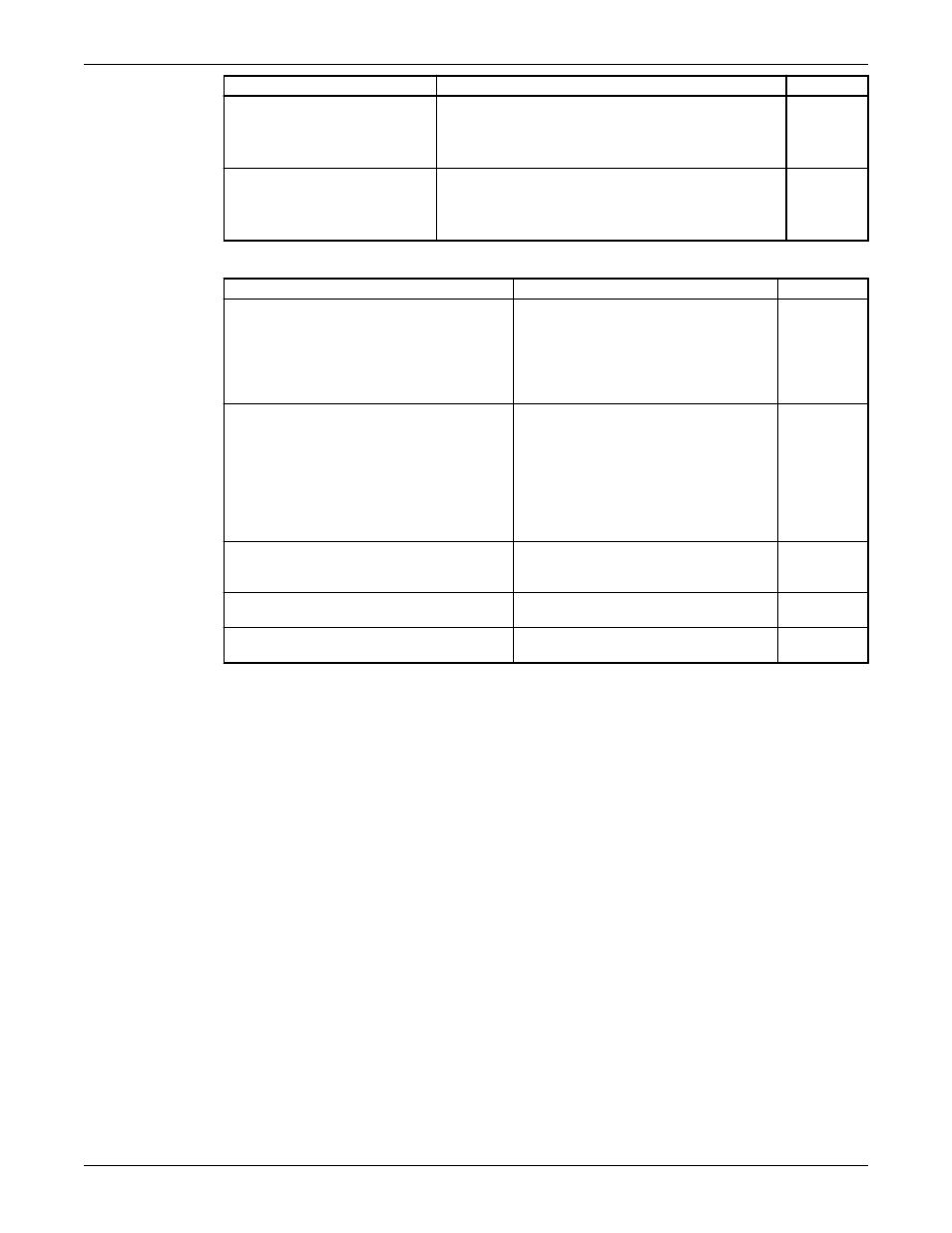
Check
Explanation/comment
Checked
If the pump handles liquids at
elevated temperatures, make sure
that the expansion loops and
joints are properly installed.
This helps to prevent misalignment due to thermal
expansion of the piping.
Make sure that all piping
components, valves and fittings,
and pump branches are clean
prior to assembly.
—
Suction and discharge piping checklist
Check
Explanation/comment
Checked
Check that isolation valves are installed in the
suction and discharge line.
Isolation valves are required for:
• Priming
• Regulation of flow
• Inspection and maintenance of the
pump
Check that check valves are installed in the
suction and discharge lines, between the
isolation valve and the pump discharge head.
The location between the isolation valve
and the pump allows inspection of the
check valve.
The check valve prevents damage to the
pump and seal due to the back flow
through the pump, when the drive unit is
shut off. It is also used to restrain the
liquid flow.
If increasers are used, check that they are
installed between the pump and the check
valve.
—
If quick-closing valves are installed in the
system, check that cushioning devices are used.
This protects the pump from surges and
water hammer.
If increasers are used, they must be of the
eccentric type.
This prevents air from collecting at the top
of the discharge pipe.
Install a partially-assembled pump
Pumps 20 feet (6 meters) or less in length are usually shipped partially assembled, with the exception of
these parts:
• Driver
• Packing
• Mechanical seal with piping
• Coupling assembly, spacer or non-spacer type
Refer to the Certified Pump Outline Drawing for the location of the anchor-bolt holes.
1. Clean the barrel flange and the bottom of the discharge head.
2. Check that all pump fasteners are tight since transportation and handling can result in bolt relaxation.
3. Install the barrel-to-discharge head O-ring.
4. Attach shackles to the discharge head lifting lugs or thread two eyebolts through the bolt holes in the
mounting flange.
5. Hoist the unit into position over the foundation.
Make sure that the shackles, eyebolts, and sling are rated to handle in excess of the pump weight. See
the outline drawing.
6. Carefully guide the unit so that it does not strike the sides of the sub-base or foundation.
7. Lower the unit until the discharge-head flange engages and rests firmly on the barrel flange, then
secure it with the capscrews provided.
8. When a lineshaft is shipped separately, complete these steps:
Installation (Continued)
18
Model VIC Installation, Operation, and Maintenance