Goulds Pumps AF (Axial Flow) (6"-36) MXR Bearings" User Manual
Page 61
AF (6-36) IOM
59
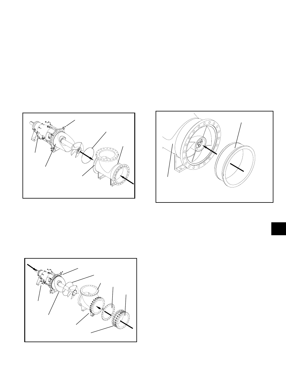
Fig. 67
Back-Pullout / Elbow or Elbow with Casing /
Liner (option)
Elbow
13. Set the pump down on a smooth flat surface to
stabilize it for assembly. Loosen the impeller adjusting
bolts (356A) so that they are clear of the rear elbow
flange. Insert the O-ring (351) into the elbow groove
and hold in place with a small amount of grease. With
the elbow held in place, slide the back-pullout into the
elbow (315A). Install the bolts (789L and 799O) that
secure the back-pullout to the elbow (315A). Be sure
to use the correct O-ring material for the pumpage,
see Fig. 67.
Elbow with Casing
14. The 700mm & 36” size pumps come with a
separate casing (100). Loosen the adjusting screws
(356A) so that they are clear of the elbow flange.
Insert O-ring (351) into the elbow groove and hold in
place with a small amount of grease. Be sure to use
the correct O-ring material for the pumpage. With the
elbow fixed, slide the back-pullout into the elbow
(315A) and install bolts (789L and 799O). Insert the
O-ring or gasket (351A) between the casing (100) and
elbow (315A). Attach the casing (100) to the elbow
(315A) using the bolts (799C) and nuts (799D). With
casing (100) slightly loose adjust casing to center the
impeller., see Fig. 68.
Liner (option)
15. If the elbow (100) or casing (100) has an optional
liner (103A) now is the time to install it. The liner may
require some effort to install try using a wooden mallet
if resistance is noticed. The liner is sealed when it is
compressed against the pipe flange and requires no
gasket. If a replacement is necessary be sure to order
the correct material for the pumpage, see Fig. 69.
DRIVE / GUARD
19. Insert the drive key (400) into the shaft (122)
keyseat. Depending on the drive type, install the
hub fasteners for a coupling or sheave to the shaft
(122). If you have a coupling halve that is
interference fit, you may need to heat it before
installing on the shaft (122). Drive instructions are
included with the data package. Follow the
manufacturer’s instructions for coupling or sheave
installation, see Fig. 70 on the following page.
20. Depending on the drive arrangement, either V-belt
or Direct Connect, use steps 21, 22 and 23, or 24,
25 and 26 respectively.
V-Belt Configuration
21. Using a crane, lift the pump into place on the sub-
base. Be careful not to damage the pump by
striking any beams or walls that may be near the
pump. If any shims were found under the bearing
housing feet during disassembly replace them at
this time. Install the pump to sub-base bolts
(500A) and remove the lifting straps or chains from
789L
799O
356A
351
315A
BACK-PULLOUT
REAR
ELBOW
FLANGE
Fig. 69
100
103A
Fig. 68
789L
799O
356A
351
100
Back-pullout
351A
799D
799C
315A
6