Re-assembly, Warning – Goulds Pumps AF (Axial Flow) (6"-36) MXR Bearings" User Manual
Page 57
AF (6-36) IOM
55
RE-ASSEMBLY
Re-assembly of the AF is done opposite the order of
disassembly with a few exceptions. Be sure the parts
are clean and free of burrs and scratches. Every
assembly step should be double-checked to ensure
proper order and technique to prevent having to
partially disassemble the step you just finished.
COOLING COIL (OPTIONAL) / SIGHT
GLASS / BREATHER AND PLUGS
The optional cooling coil is installed by first fastening
two modified male connectors (972G) to the cooling
coil cover (113B). Insert the ends of the cooling coil
(984A) through the male connectors (972G) and screw
the female connector (972H) to the male compressing
the tubing in-between. Attach the cover plate (113B)
to the bearing housing (134C) using a new gasket
(360E) and the six screws (370F) w/ O-rings (370F)
see Fig. 56.
Install the breather (113A), pipe plugs (408, 408A,
408D, 251C) and sight glass (319) in the locations
shown in Fig. 56.
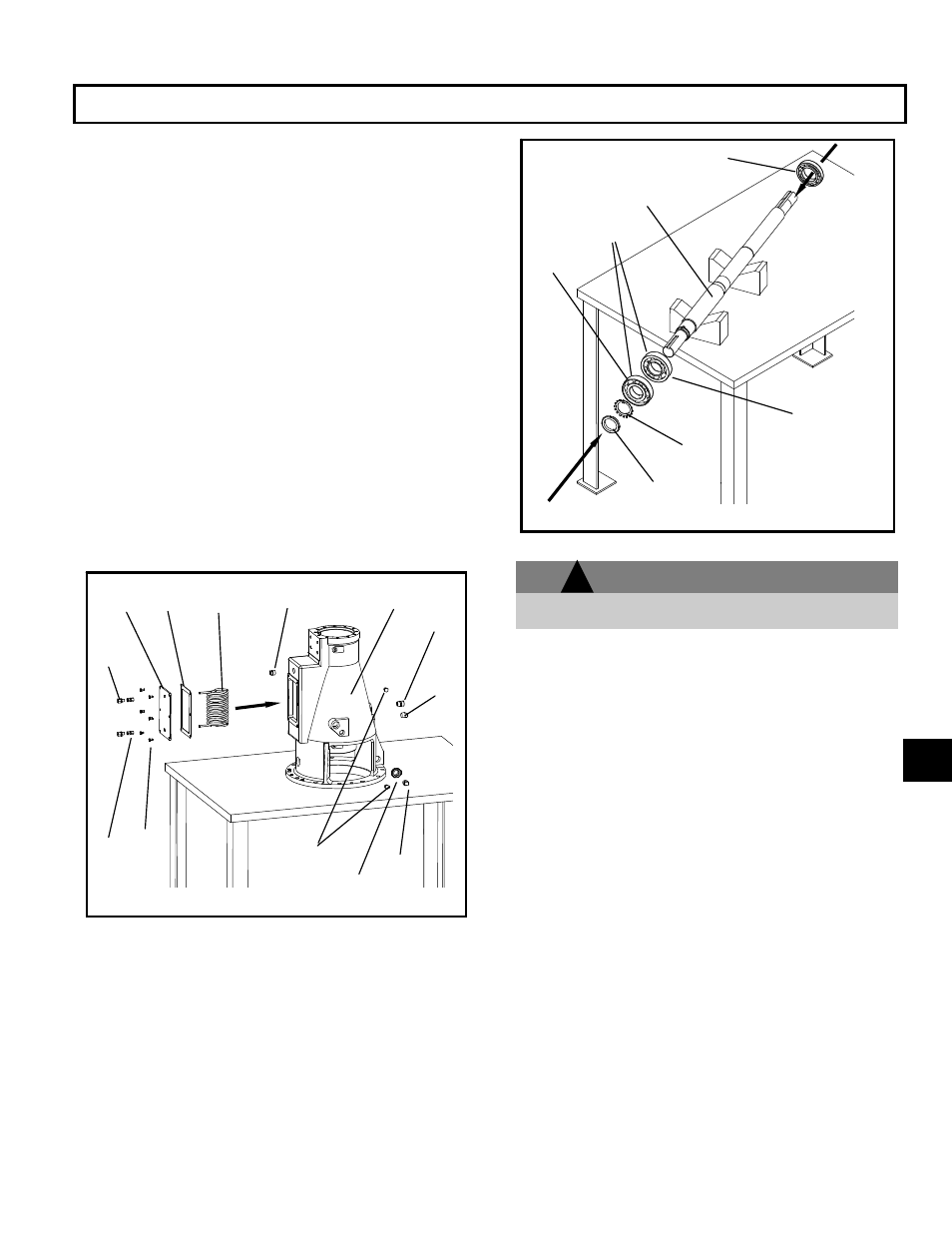
ROTATING ELEMENT
1MXR-3MXR Configurations:
1. Heat the inboard radial bearing (168C) to 225
F
using an induction heater. Slide the bearing onto
the impeller end of the shaft (122), push it on until
it rests flush and square against the shaft
shoulder, see Fig. 57 and the sectional drawing at
the end of this section.
WARNING
Use insulated gloves when using a bearing heater.
Bearings get hot and can cause physical injury.
2. Heat the inner thrust bearing (112C) to 225
F. The
thrust bearings are mounted back-to-back, so
before placing the bearing on the shaft (122) be
sure that the large diameter face of the inner race
is facing the shaft shoulder.
3. Heat the outer thrust bearing (112C) to 225
F.
Slide the bearing onto the shaft with the small
diameter of the inner race facing the inner thrust
bearing. Be sure it rests flush and square against
the inner thrust bearing.
4. Before the bearings cool install the bearing lock-
washer (382) and lock nut (136). Tighten until
snug. Re-tighten the lock nut (136) several times
before the bearing cools completely. The tapered
end of the locknut (136) should face toward the
lock washer (382). Be sure that no clearance
exists between the outer and inner thrust bearing
(112C). With the nut secure align the slots with
the lock-washer tangs and bend the lock washer
tangs into the nut slots.
5. If the pump is grease lubricated pack the inboard
(168C) and outboard bearings (112C) with suitable
grease. Make sure the races are fully packed.
Fig. 57
122
112C
136
382
INNER
THRUST
BEARING
OUTER
THRUST
BEARING
168C
Fig. 56
408
134C
972H
370F
496D
113B 360E
408A
113A
319
408D
984A
972G
251C
6
!