Warning – Goulds Pumps AF (Axial Flow) (6"-36) MXR Bearings" User Manual
Page 58
56
AF (6-36) IOM
4MXR-6MXR Configurations:
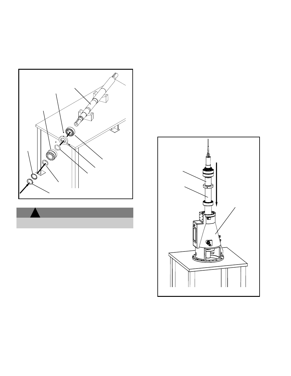
6. Heat the inboard radial bearing (168C) to 225
F
using an induction heater. Slide the bearing onto
the drive end of the shaft (122) push it on until it
rests flush and square against the inboard
shoulder, see Fig. 58.
WARNING
Use insulated gloves when using a bearing heater.
Bearing will get hot and can cause physical injury.
7. Install the oil wheel (248) by sliding it onto the
shaft with the open end facing the inboard bearing
(168C). With the oil wheel up against its shoulder
install the set screws (222N) that hold it to the
shaft (122).
8. Heat may be applied to the thrust bearing collar
(443X) if necessary to install on the shaft. Install it
with the tapered end facing the oil wheel (248).
9. Heat the thrust bearing (112C) to 225
F. Install
one row of roller bearings and the inner race on
the shaft (122). Be sure to slide the bearing on
the shaft until it is flush and square up against the
thrust bearing collar (443X).
10. While the thrust bearing is still hot install the outer
row of rollers and the outer race. Install the keyed
washer (142B), lock-washer (382) with its tang in
the groove on the shaft (122) and the lock nut
(136) with tapered end toward the lock washer
(382). Tighten the whole unit until snug. Re-
tighten the lock nut (136) several times before the
bearing cools completely. Be sure no clearance
exists between the inner race, collar (443X) and
shaft shoulder (122). With the locknut secure
align the slots with the tangs of the lock-washer
and bend the lock washer tangs into the nut slots.
11. If the pump is grease lubricated pack the inboard
(168C) and outboard bearings (112C) with suitable
grease. Make sure the races are fully packed.
BEARING HOUSING
12. Thread an eyebolt into the end of the shaft (122),
lift and lower the rotating element into the bearing
housing (134C), see Fig. 59. A collar similar to
that shown on pg. 69 should be used to prevent
misalignment of the inboard radial bearing.
26. Using screws (799F & 370Y), install the front
(239B) and rear feet (239A). Install the thrust
bearing retainer (119C), O-ring (412Y) (4MXR ~
6MXR) or gaskets (331) (1MXR~ 3MXR). See the
assembly drawing for proper shimming of
gasketed pumps. Install the screws (788Z) that
secure the thrust bearing retainer (119C) to the
bearing housing (134C), see Fig. 60.
Fig. 58
142B
168C
122
248
443X
136
382
112C
222N
Fig. 59
Rotating
Element
122
134C
!