Goulds Pumps AF (Axial Flow) (6"-36) MXR Bearings" User Manual
Page 60
58
AF (6-36) IOM
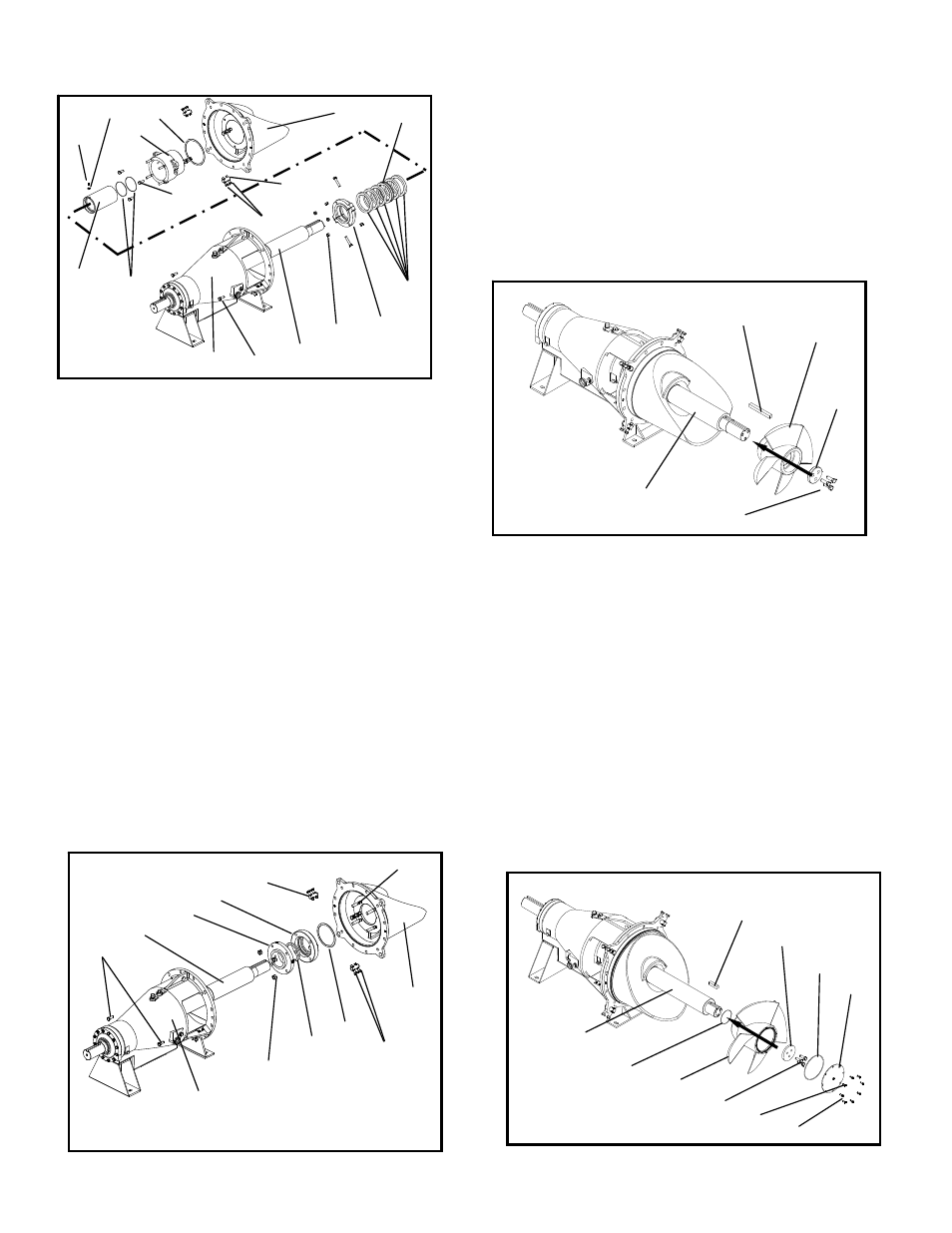
Mechanical Seal w/ Optional Adapter
16. The loose mechanical seal (383, 108) components
and gaskets (211) are slid onto the shaft (122) first
before the stuffing box cover (184) can be
installed. If the seal includes a restrictor bushing
(496B) an optional adapter (108B) will be included
with the pump. On large pumps use a sling or
hook and chain to securely support the weight of
the stuffing box cover during installation. Mount
the stuffing box cover on the bearing housing
(134C) register. Secure the stuffing box cover
(184) to the bearing housing (134C) using two
bolts (370C). Be careful not to scuff or mar the
pump shaft (122) during installation. Install the
four adjusting lugs (415) and impeller adjusting
bolts (356A). Use the upper adjusting screws
(356A) closest to the bearing housing to center the
stuffing box cover on the shaft. The seal
manufacturers instructions should be followed to
correctly install and align the mechanical seal.
Lastly, install the seal gland nuts (353) and secure
the seal to the stuffing box cover (184). Be sure
all gland quench or flush tubing is connected. see.
Fig. 64.
IMPELLER
Standard Impeller
17. Install the shaft key (178). Slide the impeller (101)
onto the shaft (122) and if necessary use a
wooden mallet to set it in place against the shaft
shoulder. Install the shaft washer (199) and
fasteners (198), tighten to lock the impeller (101)
in place, see Fig. 65.
Sealed Impeller
18. 700mm and 36” sizes use an impeller cover and
O-rings to keep pumpage out of the impeller
cavity. First, install the shaft key (178) on the
shaft. Using some silicone stick the impeller O-ring
(412A) to the back side of the impeller (101).
Slide the impeller (101) onto the shaft (122). If
necessary use a wooden mallet to set it in place
against the shaft shoulder. Install the shaft
washer (199) and bolts (198). Place the O-ring
(412T) on the cover and fasten the cover (998E) to
the impeller (101) using bolts (370M). Some
impeller covers have a pipe test plug (408H)
located on the face of the cover to test the cavity
seal after re-assembly, Re-install this plug (358I),
see Fig. 66.
Fig. 63
412D
122
220
370C
126
134C
351W
799E
105
106
184
356A
469D
178D
107
353
415
Fig. 64
370C
122
383
108B
415
134C
353
496B
211
356A
184
355
Fig. 65
101
178
122
199
198
Fig. 66
122
412A
101
198
358I
370M
998E
412T
199
178