Myron L 729II User Manual
Page 62
58
3. Slowly shake the sensor to remove air bubbles from
inside the sensor bore hole.
4. Allow 5-10 minutes for temperature to equilibrate. For
the quickest and the best results, both the sensor and
solution should be at the same temperature.
5. Turn power ON.
6. Read the display of the instrument. The display should
match the value and units of measure located on the
bottle of standard solution. If the reading is different,
adjust CALibration control on the main circuit board
until the reading matches the solution value. This will
require removal of the front panel. For removal, see
section V.C.1.a. 1-4.
7. After adjustment, turn power OFF.
8. Re-install front panel as described below in
“REASSEMBLY”.
9. To operate, turn power ON.
3. SENSOR SUBSTITUTE CALIBRATION
NIST traceable Sensor Substitutes are commonly use to verify
and calibrate Resistivity Monitor/controllers. Normally they are
not needed due to the “built-in “ electronic calibration or “Full
Scale Test”. However, your requirements may be such that a
crosscheck or verification is required. Sensor Substitutes are
available from the Myron L Company, see accompanying chart,
figure V.C.1, for part number.
If the proper Resistivity Sensor Substitute is not readily avail-
able and you can not wait for one to be delivered, one may be
constructed using the equivalent resister values listed on the
accompanying chart, figure V.C.1 and schematic, figure V.C.2.
NOTE: If you have previously performed a system calibra-
tion with either a NIST Standard Solution, or using the transfer
standard method, using this procedure will make that calibra-
tion invalid. You must decide which is more important, a system
calibration, or an electronic calibration.
1. Ensure power is OFF.
2. Using a standard slot screwdriver remove the four (4)
screws on the front panel.
3. Carefully wiggle the front panel to loosen and pull gently
toward you. Do not pull more than about 8 inches/
20CM or you could damage the wiring harness.
4. Turn the front panel around so that the back side is
facing you and set aside.
5. Locate and remove the sensor leads from the sensor
connector as shown in figure V.C.3.
6. Install Sensor Substitute with label toward transformer
as shown in figure V.C.3.
7. Turn power ON.
8. Display reading should be full scale of range. If not,
adjust CALibration control to read full scale, i.e. 0-500 KΩ
range should indicate 500, 0-10.00 MΩ = 10.00, and
0-20.00 MΩ = 20.00 at full scale. When setting digital
models with a full scale of 2000 (1999), it is advisable
to adjust Full Scale to 1990, otherwise an overrange
condition may occur.
9. After adjustment, turn power OFF.
10. Re-install front panel as described below in
“REASSEMBLY”.
11. To operate, turn power ON.
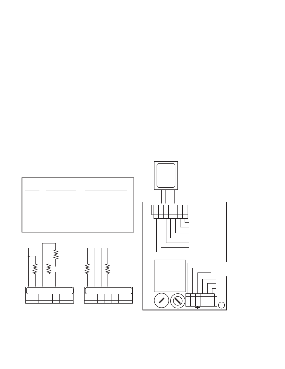
NC
CONDUCTIVITY/TDS
Figure V.C.2
5.49K 1%
X
RESISTIVITY
BK WT RD GN NU R- R+
BK WT RD GN NU R- R+
X
RESISTIVITY MONITOR/CONTROLLER
RANGE
PART NUMBER
RESISTER VALUE - X*
0-20 MΩ
0-10 MΩ
0-5 MΩ
0-2 MΩ
0-1 MΩ
0-500 KΩ
0-200 KΩ
CS-11
CS-12
CS-13
CS-14
CS-15
CS-16
CS-17
1 MΩ
500 KΩ
249 KΩ
100 KΩ
50 KΩ
24.9 KΩ
10 KΩ
*1%
Figure V.C.1
ALARM
CONTROL
RELAY
MAIN
INPUT
POWER
LINE-BLK/+DC
NEU-WHT/-DC
GND-GRN
}
}
Figure V.C.3
ELECTRICAL CONNECT DIAGRAM
CHASSIS GROUND for
OEM INSTALLATIONS ONLY
FUSE
115/230
SWITCH
L N
NC
NO
COM
0-10VDC
OUTPUT
NEU
GRN
RED
WHT
BLK
(+)
(-)
}
}
SENSOR SUBSTITUTE
LABEL TOWARD
TRANSFORMER
TRANSFORMER
CS-11
20 MEGΩ
RESISTIVITY
SENSOR
SUBSTITUTE
NIST TRACEABLE
INSTALL WITH
LABEL TOWARD
TRANSFORMER
MYRON L
COMPANY
5-01
100K 1%
10K 1%
SENSOR