Myron L 729II User Manual
Page 27
B.
4A/4AO MODULE (4-20mA OPTION)
Available only on the digital models 758II, 759II, 753II and
754II, or all analog and digital OEM Monitor/controllers.
-4A
4-20mA Self/Remote-powered Isolated output module
ordered with Monitor/controller.
4AO
4-20mA Self/Remote-powered Isolated output module
ordered separately (includes harness).
1. DESCRIPTION
The 4-20mA option gives the Series II Monitor/controller the
ability to send a signal very long distances with minimal interfer-
ences and signal degradation. The output is an Isolated 4-20mA
signal that corresponds to the full scale range of the Monitor/
controller into which it is installed. This output is easily config-
ured to be either self-powered or remote-powered as required
for your particular application.
NOTE: The maximum impedance of the user’s current input
instrument should not exceed 600 ohms.
Since the output is an isolated current loop, it is the ideal choice
for applications requiring; a control signal to be run very long
distances, systems requiring a 4-20mA input or in instances
where isolation is necessary.
As the output is isolated, and a current, it is useful for long
distance interface, especially where wiring resistances may be
high, and/or the ground potentials may differ between the sen-
sor input ground and the current receiving instruments ground.
The 4-20mA output will not be degraded in accuracy even when
the ground differences are as much as 120VAC @ 60Hz. Inter-
face wire resistance of 350Ω will not degrade the accuracy of
the output when interfaced to a typical 250Ω input impedance of
a transmitter current input device.
The output is capable of driving a minimum of 600Ω worse case,
therefore, will satisfy virtually all modern interface requirements.
Current input devices usually have an input impedance of 250Ω,
however, some older designs can have as high as 500Ω or as
low as 10Ω. This “-4A” option will drive any impedance from 0 to
600Ω without any degradation of performance.
There are two modes in which current loop transmitters operate;
Self-Powered and Remote-Powered.
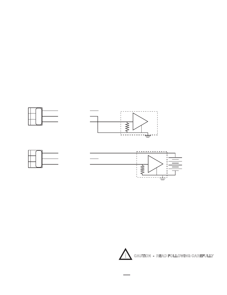
Self-Powered — the transmitter provides the power to drive
the 4 to 20 mA current. See figure III.B.1.
Remote-powered — the receiving instrument provides the
power to drive the 4 to 20 mA current. See figure III.B.2.
Specifications
Self-Powered and Remote-Powered
Drive Impedance — 0 to 600Ω
Common Mode Maximum — 120VAC @ 60 Hz
Isolation — 100pf max. to Model 750II circuit common
100pf max. to input power line
Calibration
Two multi-turn pots — Factory Set.
4mA = Zero (0)
20mA = Full Scale
Calibration is NOT required. However, if you feel you must verify
or recalibrate, see Recalibration below.
2. INSTALLATION
Briefly -
The 4-20 Module replaces the plastic display retainer plate at-
tached to the front panel.
The 4-20 Module harness is attached to the main circuit board
as marked ‘4-20’. See figure III.B.4.
The 4-20 output is wired as required - Self-powered or Remote-
powered. See figures III.B.1 & III.B.2.
WARNING: BEFORE STARTING, IF MONITOR/
CONTROLLER IS INSTALLED, ENSURE THE POWER
IS OFF. FAILURE TO DO SO COULD CAUSE DAMAGE
TO THE INSTRUMENT, AND COULD BE HARMFUL OR
Figure III.B.1
CURRENT INPUT INSTRUMENT
Self - Powered
(+)
(-)
+
-
(+)
SIGNAL OUT
POWER OUT
POWER IN
N
+
Figure III.B.2
CURRENT INPUT INSTRUMENT
Remote - Powered
(+)
(-)
+
-
(+)
SIGNAL OUT
POWER OUT
POWER IN
+
+ 35 VDC
MAXIMUM
N
SO PO PI
SO PO PI
4A (4-20mA) Wiring Options
!
CAUTION - READ FOLLOWING CAREFULLY
23