Myron L 729II User Manual
Page 35
31
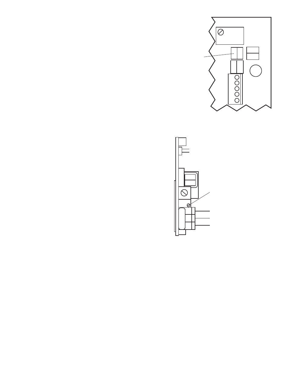
counterclockwise position. If not, turn SCO Set Point
control fully CCW - it may be 30 turns - or until it clicks.
For location see figure III.C.13.
3. Turn power ON.
4. Press BOTH the Temperature Select switch and the
Set Point switch on the front panel.
5. Adjust the TP/TPO Module Set Point Two (SP2) to
temperature as desired. See figure III.C.1.
6. Turn power OFF.
c. Hysteresis is fixed at approximately ±6°C unless
Special Ordered with adjustable control.
Hysteresis with adjustable control is variable from ±0.6 to 6°C,
see figure III.C.1 for location.
CAUTION: Adjusting the hysteresis too narrow may cause the
alarm to fluctuate (on-off) due to temperature variations causing
the relay to chatter. This condition is to be avoided, it may dam-
age the heater, chiller, etc. and will eventually damage the relay.
R
EASSEMBLY
1. Carefully reinstall the front panel, bottom first. Ensure
no wires have been pinched between enclosure and
front panel.
2. Reinstall the four (4) screws and tighten.
3. To operate, turn power ON.
Figure III.C.12
FS
INC
INC
TEMP
CONTROL
HARNESS
DEC DEC
SET POINT
CONVERSION (SPC)
SPC
Figure III.C.13
SC/SCO MODULE
(SECOND ALARM/CONTROL)
MAIN CIRCUIT BOARD NOT SHOWN FOR CLARITY
SCO SET POINT #2 ADJUST
(TURN CONTROL FULL CCW)
SPC
INC
PA
COM
RELAY #2
}
NO
NC
CM
N
O
N
C