Myron L 729II User Manual
Page 17
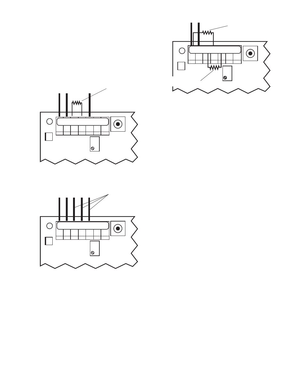
d. Install 5.49kΩ resistor at RED (RD) and the
NEUTRAL (NU) connector locations, as shown in
figure II.E.5.
5. Carefully reinstall the front panel, bottom first. Ensure
no wires have been pinched between enclosure and
front panel.
6. Reinstall the four (4) screws and tighten.
7. To operate, turn power ON.
NOTE: Recalibration will require both the solution and sensor
be at 25°C for maximum accuracy.
4. SOLID STATE OUTPUT
24 VDC Unregulated 30mA max. The following instructions are
assuming the Monitor/controller enclosure is already open.
a. Piezo Electric Alarm - PA/PAO (option)
For additional information, see Piezo Alarm under Options in
section III.I.
1. If not already installed, peel tape backing from PIEZO
and press into place per figure III.I.3.
2. Attach connector to main control circuit board per
figure III.I.4.
NOTE: If remotely mounted; cut wires and splice as necessary,
use comparable wire. Piezo requires 1/4” (6.35mm) hole in user
panel.
b. Remote Alarm - RA™ (option)
For additional information, see RA Instructions under options in
section III.J.
1. Run user supplied #22, 2 conductor speaker type wire
from Monitor/controller to RA location as necessary.
Additional wire may be ordered, part #RAW-200, see
Options & Accessories.
2. Open the RA by removing the four (4) screws.
3. Locate and remove the 8” 2 conductor wire attached
to RA.
4. At the controller, connect the extension wires to the 8”
2 conductor wire with the wire nuts provided — Black
to Positive (+) and White to Negative (-). Be sure to
first pass the wire through the user supplied waterproof
strain relief in the enclosure.
5. Plug the reddish brown female connector into the
male connector on the controller CB marked either RA
or PA (see inside case label for location). It will only go
on the connector one way.
6. At the RA, connect the wires to the connector — Black
to Positive (+) and White to Negative (-).
7. To test, simply turn on the controller and adjust
controller set point until the alarm/piezo sounds off. If
controller is not yet connected to a functioning sensor,
on conductivity/TDS controllers it will be necessary to
press and hold the Full Scale test switch.
The black button on the front of the RA will mute the
piezo alarm for approximately three minutes or until
you improve the water quality (readjust controller set
point). The piezo alarm will continue to sound off every
three minutes until the user has improved the alarm
condition inside the controller. If three minutes muting
is fine for your application, skip to step 9.
8. If three minutes is too long or too short, adjust time
delay control inside RA until desired mute time is achieved
(adjustable from approximately 6 seconds to
10 minutes).
9. Replace the bottom of the RA, and secure RA to the
surface you have selected for its installation.
NOTE: If the RA does not sound off;
1. Check the polarity of the extension wire connections.
2. Be sure the controller is actually switching (relay will
click).
13
BK WT RD GN NU R- R+
FS SW
3S
SENSOR LEADS
INSTALL 10KΩ
RESISTOR HERE
CAL
REMOVE THESE
THREE LEADS
FS SW
BK WT RD GN NU R- R+
3S
SENSOR LEADS
CAL
SENSOR LEADS
FS SW
3S
CAL
INSTALL 100KΩ
RESISTOR HERE
INSTALL 5.49KΩ
RESISTOR HERE
BK WT RD GN NU R- R+
Conductivity/TDS Main CB Assembly
Figure II.E.3
Resistivity Main CB Assembly
Figure II.E.4
Resistivity Main CB Assembly
Figure II.E.5